


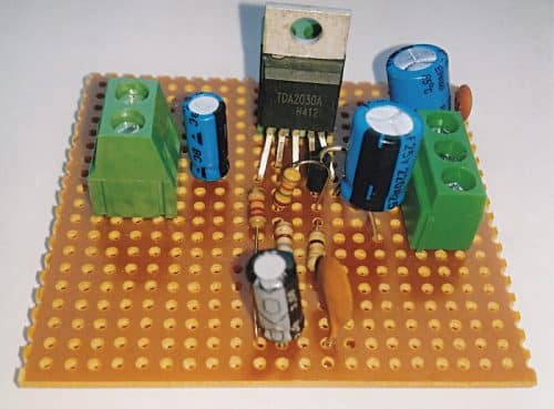
 Here is a simple mono audio amplifier using a single 5-pin IC TDA2030A. This IC is inexpensive and easily available in the market. The author’s prototype, which gives 14W output, is shown in Fig. 1.
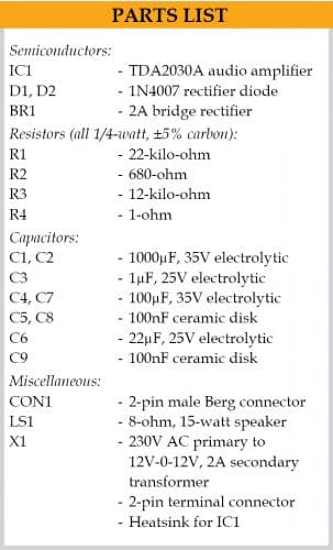
The circuit diagram of the audio amplifier is shown in Fig. 2. It comprises TDA2030A audio amplifier (IC1), two 1N4007 rectifier diodes (D1 and D2), four resistors (R1 through R4), nine capacitors (C1 through C9), 15-watt speaker (LS1), bridge rectifier (BR1) and a few other components.
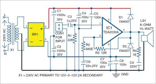
For the power supply, the amplifier uses 230V AC primary to 12V-0-12V, 2A secondary transformer (X1). Two electrolytic capacitors C1 and C2 are used as filters for DC output voltage. The amplifier requires a dual ±12V power supply, which can be obtained across transformer X1 and bridge rectifier BR1. The +12V supply is connected to pin 5 and -12V to pin 3 of IC1.

Pin 1 of TDA 2030A is connected to the audio input terminal through electrolytic capacitor C3 (1µF/25V). Loudspeaker LS1 is connected to output pin 4 of IC1.
Construction and testing
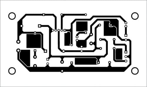
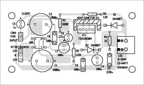
An actual-size PCB layout for the audio amplifier circuit is shown in Fig. 3, and its components layout in Fig. 4. After assembling the circuit on PCB, connect audio input from computer/laptop/mobile phone across CON1 and the 8-ohm, 15-watt speaker across LS1. Connect the transformer’s secondary output (12V-0-12V) to the PCB and its primary to 230V AC mains.
Download PCB and Component Layout PDFs: click here
You can also construct your amplifier on veroboard (5cm×7cm). Mount IC1 in the middle of veroboard. Use a 2-pin connector on the left side and a 3-pin connector on the right side of the veroboard. The 2-pin connector is used for audio input, and the 3-pin connector is for dual power supply. Solder all the remaining components like resistors, capacitors, diodes, etc, using a low wattage soldering iron. You will need a suitable heat sink for IC1.
After connecting the dual power supply (12V-0-12V) to the circuit, you can test the circuit. For that, take a metal screwdriver and gently touch on the input terminal. You will hear a humming sound from the speaker, which means your amplifier is working. Note that the output power of amplifier will depend on the power supply.
Connect audio input at CON1 from any audio source such as MP3 player, laptop, or mobile phone.
Raj K. Gorkhali is a regular contributor to EFY and an electronics hobbyist
Respected Sir,
May You kindly inform about the model number of PCB (Printed Circuit Board ) is used here because I am much interested to build this project on PCB for our Engineering project . If possible a pack of spares including parts to be informed for submitting orders.
Yours affectionately,
Rahit kumar Roy
Contact no- 9007093455
Howrah-700310.
PCB is not available right now. You can easily assemble the circuit either on a veroboard(general-purpose PCB) or on breadboard. The rest of the components can be purchased from kitsnspares.com or contact at [email protected]
Sir, can I use 1N4001 instead of 1N4007 for D1&D2?
Yes. You can use 1N4001 in place of 1N4007.
Regards
Dear Sirs,
the download link for the PCB and Component Layout seems to be broken.
Please can you fix this?
Kind Regards
Mitsos
Kindly refresh the page and retry.