


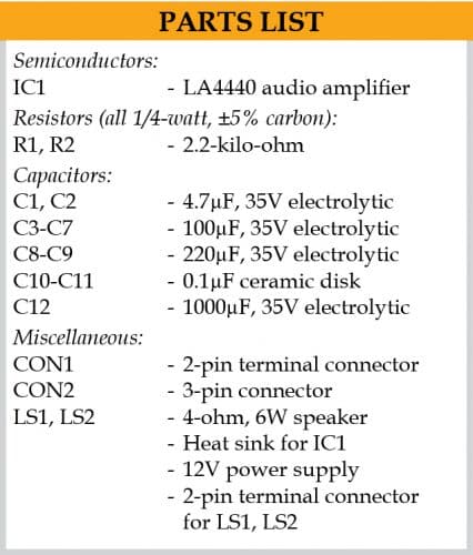
 Here is a simple project of a 6W+6W stereo amplifier using a 14-pin LA4440 IC. This amplifier can deliver an output power of 6W on a 4-ohm speaker (6W each on the left and right channels). The amplifier operates on a 12V power supply.
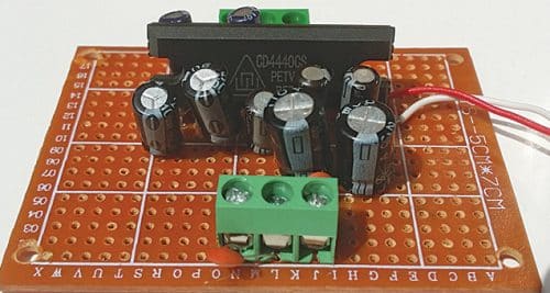
Except resistors R1 and R2, all the external components used in the circuit are electrolytic capacitors. The author’s prototype is shown in Fig. 1.
Full Video Explaination:

Circuit and working
The circuit diagram of the 6W+6W stereo amplifier is shown in Fig. 2. It is built around LA4440 (IC1), two loudspeakers (LS1 and LS2), and a few other components.
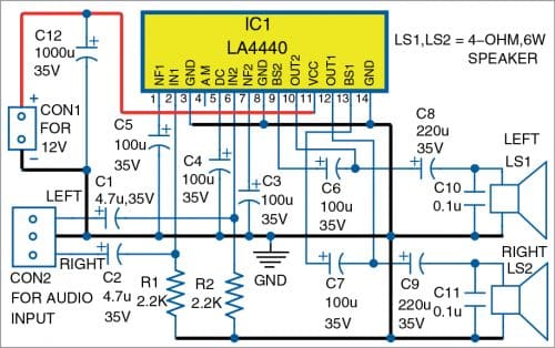
Pin 11 of IC1 is connected to the +12V power supply. The electrolytic capacitor C12 (1000µF/35V) is connected between +12V and ground to act as a filter.
The left speaker (LS1) is connected to pin 10 of IC1 through electrolytic capacitor C8 (220µF/35V). The right speaker (LS2) is connected to pin 12 through electrolytic capacitor C9 (220µF/25V).
A 3-pin connector (CON2) is provided for connecting the audio input signal. The left channel audio input is connected to pin 6 of IC1 through capacitor C1 (4.7µF/35V), and the right channel input is connected to pin 2 of IC1 through capacitor C2 (4.7µF/35V).
Construction and testing
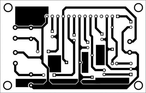
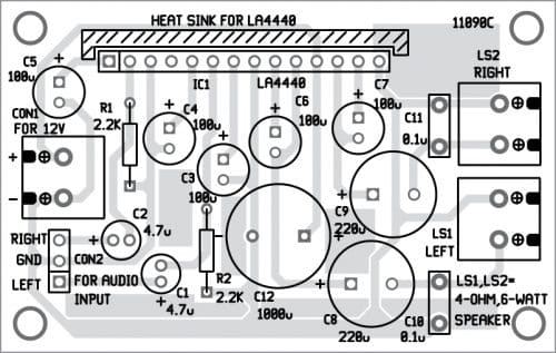
You can assemble the circuit on a 5cm×7cm veroboard or on a PCB whose actual-size layout is shown in Fig. 3 and the components layout in Fig. 4.
Download PCB and Component Layout PDFs: click here
First, collect all the components like electrolytic capacitors, resistors, IC LA4440, 3-pin connectors, wires, etc. Then, take a 25-watt soldering iron and solder all the components, as shown in the circuit diagram. Solder a 3-pin connector on the PCB/veroboard for audio input. The middle common terminal of this connector is to be connected to the ground.
Mount LA4440 IC in the middle of the veroboard. If the PCB layout is used, place the IC in the space provided for it. Now solder all the electrolytic capacitors and resistors as per the circuit diagram. Mount two 2-pin terminals for connecting LS1 and LS2 speakers.
Use a suitable heat sink for LA4440 IC. Connect the left and right channel audio inputs across CON2. Connect a 4-ohm, 6W speaker each across LS1 and LS2. CON1 is used for connecting 12V regulated power supply.
Calibration
You’ll need a 12V battery or an AC/DC adaptor to test your final prototype. You may also need an AF signal generator.
Feed AF signal generator output to the left input channel at CON2. You’ll hear the AF tone signal from the left speaker. Similarly, connect signal generator output to the right input. You’ll hear AF tone from the right speaker.
You may also connect 22-kilo-ohm volume controls to the left and right input terminals. Your 6W+6W stereo amplifier is now ready for use.
Raj K. Gorkhali is an electronics hobbyist and a regular contributor to EFY
Can I add a bass, treble and volume control in this circuit
Very fine tech. Guide lines
Thank you for your valuable feedback.
The answer is yes and no. Yes, you can modify it with additional circuit but you cannot use the same PCB as given here.