


 MicroPython is similar to Python 3, but it is meant for microcontrollers. MicroPython comes with an interactive Read-Evaluate-Print-Loop (REPL), which is an amazing feature that allows us to connect to a microcontroller, execute code quickly without the need to compile or upload code, and gives immediate feedback. Also, most importantly, the community support available for it makes the use of this firmware easier.
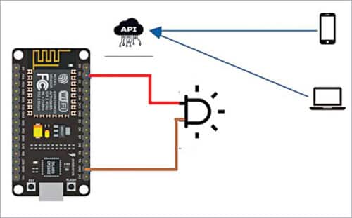
ESP8266 is a low-cost Wi-Fi module that is ideal for DIY projects involving the internet of things (IoT). As MicroPython is easy to use, which is important for beginners, it can be programmed easily. But the default firmware of ESP8266 and other ESP Wi-Fi boards are different. In this DIY project, we flash the MicroPython in Node MCU board and use the MicroPython to program the board and control its GPIO over network using Pico framework.

Flashing MicroPython firmware on the board
In order to use the PicoWeb framework and program the ESP in MicroPython to control GIPO on Node MCU, we need to erase the current firmware on ESP chip in the Node MCU. We can download the MicroPython firmware from its official website, which is in .bin format. The official website for downloading MicroPython firmware for the board is: http://MicroPython.org/download/#esp8266
After downloading the firmware, we need to first erase the current firmware. For that, estool is used to erase or flash new firmware into the ESP board. To install esptool, open the command prompt and run the following command and install the esp tool:
pip install esptool
Now, we need to connect Node MCU to the system and identify the port to which it is connected. If you are using a Linux based system, the command below will help you identify the port:
dmesg | grep tty
Next, we need to clean the board before flashing the MicroPython firmware with the below syntax. Please note, the port identified in the above step is used in the syntax as –p.
~/.local/bin/esptool.py -p /dev/ttyUSB0
erase_flash
Now, we can flash the MircoPython firmware and open the folder where the MicroPython firmware has been downloaded. Then, copy the path and file name of that .bin firmware file and flash it to the Node MCU board using the following command. (You need to change the path and filename of the firmware in the command.)
~/.local/bin/esptool.py –port /dev/tty
USB0 –baud 460800 write_flash –flash_
size=detect 0 esp8266-20210202-v1.14.bin
Note. esp8266-20210202-v1.14.bin is the firmware name downloaded, which needs to be replaced with the name of the firmware file in your system.
Wola! The board is ready, so we can enter the REPL prompt and explore. But to enter the REPL prompt we need another CLI tool, named picocom, which can be installed through the command below:
sudo apt-get install picocom
Next, use the syntax below, which will display some information on the ESP board. Press ctl+B to enter the REPL prompt.
picocom /dev/ttyUSB0 -b115200
The command to soft reset the board from the REPL prompt is ctl+D
Pushing the file from your system onto the board will require cli tool adafruit-ampy. To install it in your system, use the following syntax:
pip install adafruit-ampy
pip install adafruit-ampy –upgrade
Note. In some cases, you might face issue with picocom. In that case, you can use any serial terminal and monitor to install the pico framework. Also, after flashing the MicroPython, the board may sometimes not get connected to Wi-Fi and the internet and show an error. In that case you need to follow the instructions given under the network setup section below.
Setting up the network and connecting to Wi-Fi
Open the serial terminal and give the commands mentioned below to connect to the Wi-Fi network:
import network
sta_if = network.WLAN(network.STA_IF)
ap_if = network.WLAN(network.AP_IF)
sta_if.active(True)
sta_if.connect(‘<your SSID>’, ‘<your
key>’) # Replace the SSID with your
Wi-Fi network name and key with your
network password
sta_if.isconnected()
sta_if.ifconfig()
Now, with the Node MCU connected to Wi-Fi, we can check its IP address using following command and note the IP address:
sta_if.ifconfig()
It gives an output like:
(‘192.168.0.2’, ‘255.255.255.0’,
‘192.168.0.1’, ‘8.8.8.8’)
Setting PicoWeb framework of MicroPython
We are now ready to install the PicoWeb, which is a micro web framework for MicroPython. If you are acquainted with Flask web framework in Python, you will find it similar to work with. Two important features of PicoWeb are:
- Asynchronous, which means it can handle multiple concurrent requests.
- Small memory usage.
To install the framework in Node MCU, clone the repo to a location in your system using the code:
$ git clone https://github.com/
peterhinch/MicroPython-samples
Dependencies of PicoWeb framework
To install the framework onto the board, we need to first install a few dependencies. Open the REPL prompt, as mentioned earlier, and install the packages as mentioned below:
$ import upip
$ upip.install(‘MicroPython-uasyncio’)
$ upip.install(‘MicroPython-ulogging’)
$ upip.install(‘MicroPython-pkg_resources’)
$ upip.install(‘utemplate’)
Step out of REPL, using ctl+A+X, and copy some file from the local system into the board. Move to the folder where the PicoWeb repo from git is downloaded, check out for the files __init__.py and utils.py. Copy these files to the PicoWeb directory on the board. To do this, make use of the other cli tool, adafruil-ampy, which was installed earlier.
Step 1. Create the PicoWeb directory using the code:
$ ampy –port /dev/ttyUSB0 mkdir picoweb
Step 2. Copy the files from the local system to the PicoWeb directory on the board using the code:
$ ampy –port /dev/ttyUSB0 put __init.py
/picoweb/__init__.py
$ ampy –port /dev/ttyUSB0 put utils.py
/picoweb/utils.py
Creating API endpoints using PicoWeb framework
Now, we need to create the Python script by the name main.py, which will be done in two steps. First, by connecting to the available Wi-Fi and, second, by creating the api endpoint to control GPIO pin state of the board. We will also create an access point (AP) for the board, so that if there is no Wi-Fi available, we can still connect to the board AP and control the state of the GPIO pins.
sudo nano main.py
Now, copy the following code in main.py file:
import picoweb
import network
from machine import Pin
import time
ip=[]
app = picoweb.WebApp(__name__)
#create the Access Point
ap = network.WLAN(network.AP_IF)
ap.active(True)
ap.config(essid=’espAP’,
password=’espAPpassword’)
myip = ap.ifconfig()
print(myip)
#connect to the available wifi networks
station = network.WLAN(network.STA_IF)
station.active(True)
station.connect(“wifi-network-name”,
”wifi-network-password”)
myip2 = station.ifconfig()
print(myip2)
def qs_parse(qs):
parameters = {}
ampersandSplit = qs.split(“&”)
for element in ampersandSplit:
equalSplit = element.split(“=”)
parameters[equalSplit[0]] =
equalSplit[1]
return parameters
#create the api endpoint to control the
pin provided as parameter on API call
@app.route(“/pin_ctl”)
def index(req, resp):
queryString = req.qs
parameters = qs_parse(queryString)
print(parameters)
x= int(parameters[‘pin’])
pin = machine.Pin(x, machine.Pin.OUT)
pin.value(0)
time.sleep(0.5)
pin.value(1)
time.sleep(0.5)
pin.value(0)
time.sleep(0.5)
pin.value(1)
time.sleep(0.5)
yield from picoweb.start_
response(resp)
yield from resp.awrite(“done”)
if __name__ == “__main__”:
app.run(debug=True,host=”0.0.0.0”,
port=80)
Press ctrl+x and then Y to save the code. Copy this main.py file to Node MCU board using the following syntax:
ampy –port /dev/ttyUSB0 put main.py
Connecting and operating from anywhere
Connect the LED to GPIO pin of Node MCU to test the API.
Login to the Wi-Fi homepage and check the IP address assigned to the device. Enter the address in any browser and add at the end the pin you want to control as parameter, like the example below:
$ http://192.168.1.14/pin_ctl?pin=3
To control the LED, we may connect it to GPIO 10 in the circuit diagram and run the following URL in web browser:
http://192.168.1.14/pin_ctl?pin=10
Download source code
Joy Maitra is Senior Technical Architect at Hexaware Technologies. He is a technology enthusiast and an open source contributor