


 Embedded system project that generally involves a microcontroller unit (MCU) user interface (UI) is a common and inevitable requirement. The simple form of arriving this option of UI is with the help of a monochrome LCD, which serves as a basic output device and a matrix keypad interface for accepting inputs from the user. In fact, majority of the UI designs are with 2×16 LCD ASCII compliant display, typically JHD162A along with either 4×4 or 4×3 matrix keypads.
Here, we start with the development of a device driver for a matrix keypad, typically written in embedded-C for microcontroller. We will consider an 8-bit AT89S52 MCU (works well for any C51 MCU), which is easily available and whose architecture is familiar to many of us. We will implement a C driver for scanning a key in the polled mode first and see how to test it without implementing or coupling the output driver (LCD).

We shall then investigate the design aspects of converting this driver by binding/locking it into an asynchronous external interrupt pin (/INT0 pin) and present the implementation and testing aspects involved in achieving driver in embedded C. It is advised to consider further aspects with Keil µVision 5 IDE with C51 cross-compiler (that support legacy C51 microcontroller families) installed in Windows 10 host PC along with simulation software such as Proteus 7.7 or above for validation.
The project has four parts where the source program (Project1 through Project4) of each part is written in embedded C programming language. The hex code generated through Keil µVision 5 IDE is used for simulation and verification using Proteus software.
Before we dig into the technicality, we need to understand the need for this conversion. Since majority of the embedded projects deal with this standard polled-loop driver for keypad, the need to convert arises in following cases:
(a) When the MCU is expected to handle the traffic over serial (typically UART) port for achieving networking. Let us consider an example of handling the data using GSM’s ASCII terminal commands (AT) in the form of SMS. While the MCU is busy in handling this SMS traffic using handshaking options, if user presses any input, forcing the microcontroller’s attention, the traditional approach of polled-loop driver fails to recognise the user inputs. This requirement causes a serious problem when the user is attempting to configure the data and traffic is flooding over networking (in this case serial) interface.
(b) If the MCU is busy in performing the sensor data processing, either using the off-chip ADC interface option or on-chip ADC register polling, and the user is triggering an input using the input device. In this case also, the user attention will be unanswered as the MCU is already busy in sensory task.
Polled mode 4×3 embedded C driver and its validation for C51 MCU
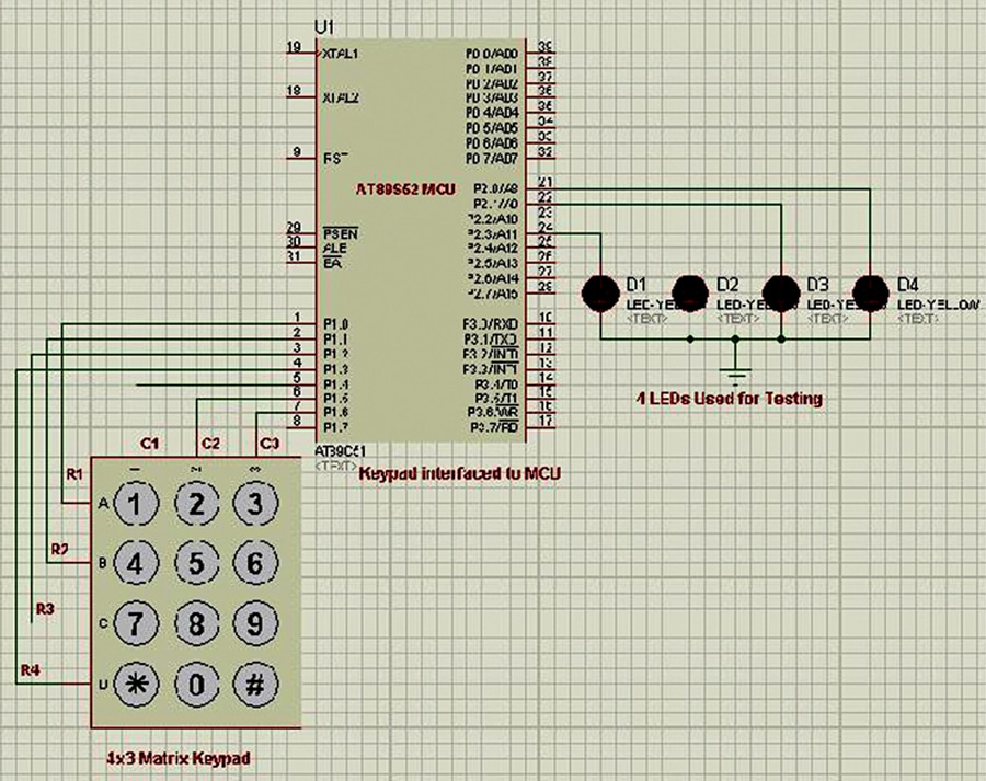
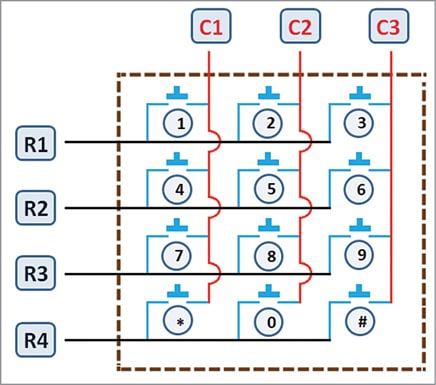
Let us consider the 4×3 matrix keypad with four rows and three columns being connected to Port 1 of AT89S52 MCU, as shown in Fig. 1. This is basically the connections in Proteus simulation software. The four LEDs are used only for testing and are connected to P2.0 through P2.3. A typical keypad layout diagram is shown in Fig. 2. The polled-loop key-scanning algorithm is very simple and straightforward, as shown in steps 1 through 7 given below:
Step-1: Configure the columns as inputs (logic-1) and rows as outputs (logic-0)
Step-2: Start polling the KeyScan by looking for any change in column (1 to 0)
Step-3: Is there any change in columns (i.e., C1=0 or C2=0 or C3=0)
If yes,
then, go to Step – 4.
else
Go to Step-2.
Step-4: Make R1=0 and keep R2=R3=R4=1 and,
If C1=0 then,
pressed key is – ‘1’ and return.
else if C2=0 then,
pressed key is – ‘2’ and return.
else if C3=0 then,
pressed key is – ‘3’ and return.
else
go to step – 5:
Step-5: Make R2=0 and keep R1=R3=R4=1 and,
If C1=0 then,
pressed key is – ‘4’ and return.
else if C2=0 then,
pressed key is – ‘5’ and return.
else if C3=0 then,
pressed key is – ‘6’ and return.
else
go to step – 6:
Step-6: Make R3=0 and keep R1=R2=R4=1 and,
If C1=0 then,
pressed key is – ‘7’ and return.
else if C2=0 then,
pressed key is – ‘8’ and return.
else if C3=0 then,
pressed key is – ‘9’ and return.
else
go to step – 7
Step-7: Make R4=0 and keep R1=R2=R3=1 and,
If C1=0 then,
pressed key is – ‘*’ and return.
else if C2=0 then,
pressed key is – ‘0’ and return.
else if C3=0 then,
pressed key is – ‘#’ and return.
else
go to step – 2
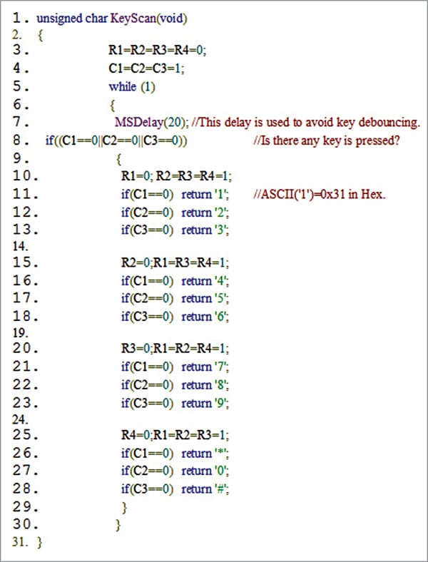
The implementation of this first part (Project1) in embedded C function is shown in Fig. 3. Upon any key press, the ASCII equivalent of the pressed key is identified and is returned. Hence, in the testing of the circuit given in Fig. 1, the lower nibble alone is sufficient as the LEDs indicate the pressed digit.
As an example, if the user presses key-‘1’, the ASCII of ‘1’, which is 0x31, i.e., 0110 0001, is shown on the LEDs. In the same way, all the keys of the keypad may be tested by observing their equivalent binary outputs on LEDs.
Let us now look at the approach of converting the above polled-loop driver by binding the interrupt and demonstrate the process of context switching from the application to interrupt service routine (ISR), and vice-versa.
Circuit diagram for interrupt-driven keypad
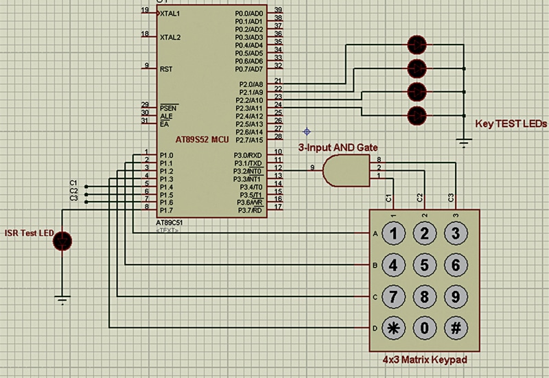
There are two external interrupt pins /INT0 and /INT1 of AT89S52, which are available as alternate-pin functions of the P3.2 and P3.3 GPIOs, respectively. Among these, let us consider usage of /INT0 pin, the P3.2 pin. A three-input AND gate 4073 IC is used such that its output must be connected to /INT0 (P3.2), while the inputs are connected to the three columns C1, C2, and C3, as shown in Fig. 4.
Implementation of interrupt-driven driver
For achieving the key input, as the columns were locked to interrupt pin, any key pressed will result into a change of column signal and thereby generate an interrupt at /INT0 pin. We must enable the interrupt /INT0 pin by configuring the IE register. Moreover, we must configure it as an edge-triggered type of interrupt using TCON register in main application.
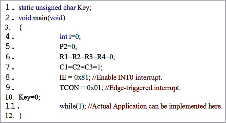
The basic configuration in the code for Project3 is shown in Fig. 5. The MCU’s C-ISR function ‘Keypad_ISR’ is implemented as indicated in Fig. 6.
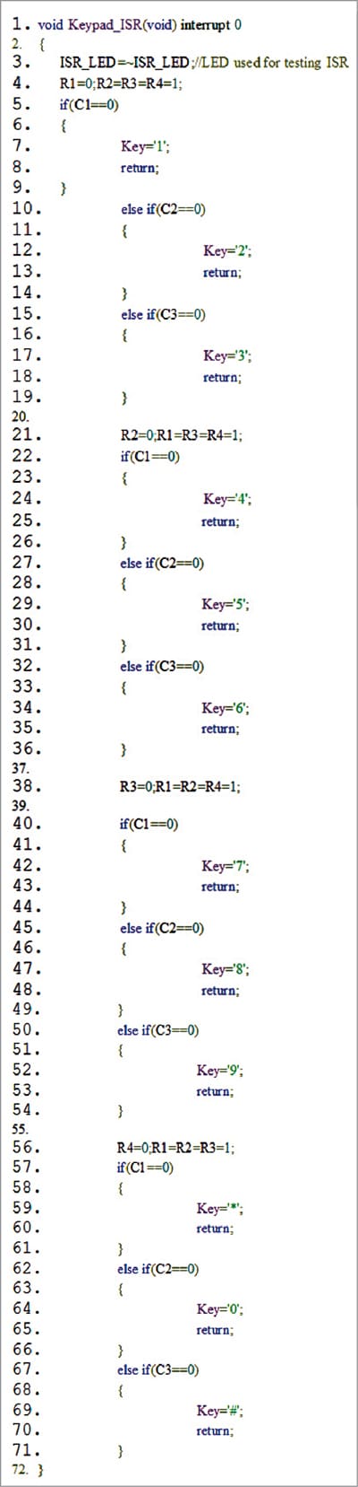
Some very important observations of the implemented ISR are:
- The interrupt must be configured as edge triggered. This is achieved in AT89S52 by configuring TCON register. Otherwise, even for a single press the interrupt will keep on running as if multiple events are occurring.
- An interrupt service routine function must not return any value. Hence, we use the concept of global shared resource, which in our case will be the global variable. In the implementation, the variable ‘Key’ will be acting as a shared resource. Notice that this shared resource is accessible not only in the main but also in the ISR.
- In the implementation given here an LED is intentionally connected to the unused GPIO P1.7 pin of AT89S52, which will toggle upon the key press due to line-3 of Fig. 6.
- Whenever a key is pressed by the user, the corresponding column status in the keypad will be changed to 1. As a result, the interrupt will be triggered, and the application will be paused as it enters into /INT0 ISR. This process is called hardware context switching. Notice that during this time, the system stack will be used. (Bank-1 in RAM)
- Inside the ISR, the actual checking or identifying the specific row’s key, which is responsible for the key press, is detected and the confirmed key is kept in the shared resource variable ‘Key’ and the ISR ends by forcing it to return. The suspended application will now be ready by context retrieval using stack’s POP operations.
- The pseudo-code shown in Fig. 7 is proposed for detecting a valid key pressed in main code for further application development.
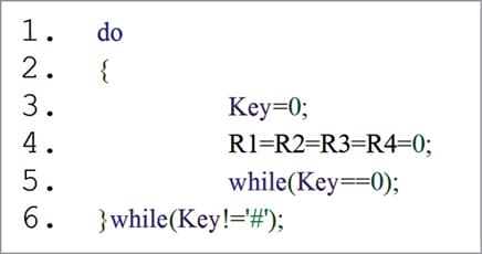
Fig. 7: Pseudo-code source listing for detecting a keypress in main application - Another important inference is that there will be no key debouncing problem, unlike in polled-loop keypad. As a result, the intentional delay for every consecutive key press is not necessary.
By considering this approach of interrupt-based keypad driver, one can implement and achieve the real-time response for UI without porting the RTOS into the MCU. This is because the ISR will run irrespective of what the application is doing, forcing the CPU’s attention. Therefore, as a result if the design is done with this recommended UI, apart from achieving the real-time response, the memory footprint (both Flash and RAM) is also greatly reduced.
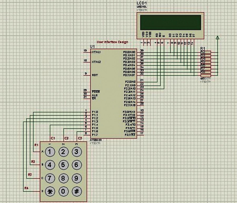
After downloading the source programs from EFY website, using circuit shown in Fig.8 along with Project2, the polled-loop application is tested with any 4-digit input as user ID and ‘1982’ as password. The ISR-locked keypad driver is tested using Fig.4 and Project3. Finally, the same application with LCD is tested using Fig. 9 and Project4.

Download Source Code
N. Abid Ali Khan is Assistant Professor in the Department of ECE at Vasavi College of Engineering (Autonomous), Hyderabad. He has been working on power-efficient embedded networking architectures and is passionate about microcontrollers, ARM, RTOS, embedded systems, and programming

Sir, Can I use TTL 3 input AND gate SN74LS11 instead of CMOS 3 input AND gate CD4073?
Sir, Thank you for the useful and informative project.
In Figure. 1 port P1.4 is not connected with the keyboard. Similarly LED D2 not connected to microcontroller and cathode to GND.
Figure. 8 and Figure. 9 uses AT89C51.