Here is a simple 4W audio stereo power amplifier using a ten-pin LA4601 IC. Only a few passive components, including ceramic and electrolytic capacitors, are used in this circuit. The 9V DC power supply helps obtain 4W stereo output.
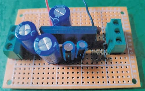
The authors’ prototype of the hi-fi stereo audio amplifier is shown in Fig. 1. Its circuit diagram is shown in Fig. 2. The amplifier is built around LA4601 (IC1), 5V regulator 7805 (IC2), two loudspeakers (LS1 and LS2), audio input source and a few other components.

Pin 1 of IC1 is connected to the right speaker (4ohm, 4W) through electrolytic capacitor C4 (1000µF), and pin 3 is connected to the left speaker (4ohm, 4W) through capacitor C5 (1000µF). Pins 4 and 2 of IC1 are connected to +9V and ground, respectively.

Pins 8 and 10 of IC1 are left and right audio input pins connected to four-pin connector CON1 through the respective input capacitors.
Construction and testing
A PCB layout of the stereo power amplifier is shown in Fig. 3 and its components layout in Fig. 4. You can also construct the circuit on a 5cm×7cm veroboard.
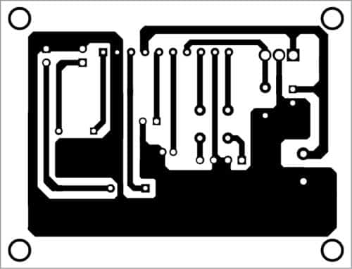
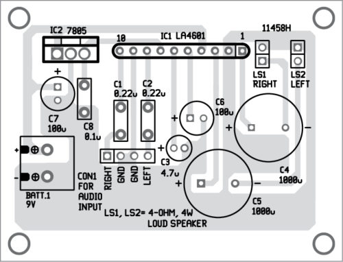
Download PCB and component layout PDFs: click here
If you are using a veroboard, place IC1 in the middle of the veroboard. Take a 25-watt soldering iron and gently solder IC1 on the veroboard. Solder IC2 at an appropriate location on the veroboard. Then, mount all remaining components on the veroboard. It is recommended to use appropriate heat-sinks for IC1 and IC2.
Next, calibrate and adjust the amplifier. Connect LS1 and LS2 to the PCB or veroboard. Connect audio input to CON1. Now, connect 9V DC power supply to the amplifier. Ensure you get five volts at output pin 3 of IC2 or at pin 7 of IC1 using a multimeter.
Take a metal screwdriver and gently touch at input pins 8 and 10. You will hear a humming sound from right and left speakers on touching on right and left inputs, respectively. The amplifier is now working and ready to use.
You may connect the amplifier to any audio source including MP3, laptop or cellphone.
Note
Pin 7 of IC1 must be high or connected to 5V source. If it is connected to GND or left open, the amplifier will be in mute mode.