


 This laser communication system transmits sound or music signals through a laser beam. The intensity of the laser beam changes with the amplitude of the sound signal. The variation in the intensity of the laser beam is converted into a variation in the voltage level by using a calculator’s solar panel. The voltage variation on the solar panel is amplified by a low-voltage audio power amplifier LM386 and reproduced by a speaker. The maximum output of audio amplifier LM386 is 1 watt, while its voltage gain is 20 to 200.
Laser communication system circuit
The circuit consists of a transmitter and a receiver. Both the transmitter and the receiver are built around IC LM386, powered by a 9V battery.
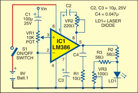
Fig. 1 shows the transmitter circuit. Here a laser diode (LD1) with maximum operating voltage of around 2.6V DC and maximum operating current of 45 mA is used to transmit the audio signal. The voltage divider network formed by R2, R3 and VR3 keeps the voltage as well as the current for the laser diode in the safe region.

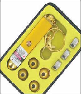
In place of the laser diode, you can also use a laser pointer. Remove the battery from the laser pointer. Extend two wires from terminals of LD1 and connect them to the battery terminals of laser pointer. The spring inside the laser pointer is the negative terminal. The output power of the laser pointer is 5 mW. Take care while working with laser, as direct exposure to the laser beam can be hazardous to your eyes. Point the laser beam to the solar panel.
Potmeter VR1 (10-kilo-ohm) is used to change the level of the input audio signal. The audio input (Vin) is taken from the preamplifier output of the music system (CD player, DVD player, etc). Capacitor C2 and preset VR2 are used to vary the gain of the LM386.
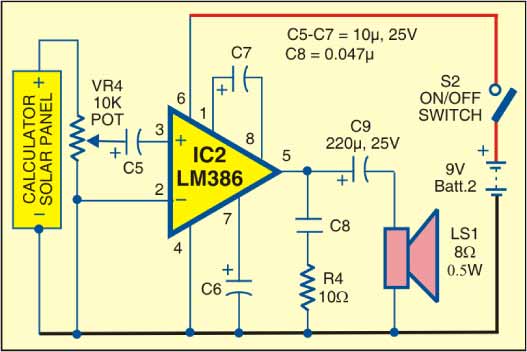
Fig. 2 shows the receiver circuit. The audio signal transmitted by the laser diode (LD1) is received by the calculator’s solar panel and amplified by IC2. The gain of the amplifier is fixed by capacitor C7. Preset VR4 is used to change the signal level from the solar panel. This signal is fed to input pin 3 of IC2 through coupling capacitor C5 so that the DC value from the solar panel can be eliminated. The amplified output from IC2 is fed to the speaker, which plays the music from the CD player connected at the input (Vin) of IC1.
Assemble the transmitter and receiver circuits on separate PCBs and enclose in suitable cabinets. In the transmitter cabinet, fix two terminals for connecting the audio signal. Fix switch S1 on the front panel and the laser diode (LD1 or laser pointer) to the rear side of the cabinet. Keep the 9V battery inside the cabinet.
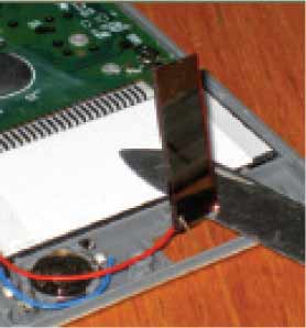
In the receiver cabinet, fix the calculator’s solar panel to the rear side such that the transmitted beam directly falls on it. Fix switch S2 on the front panel and the speaker to the rear side. Keep the 9V battery inside the cabinet. Refer Figs 3 and 4 for the laser pointer and calculator’s solar panel.
After assembling both the circuits, orient the laser diode (or laser pointer) such that the transmitted laser beam directly falls on the solar panel. Use shielded wires for connecting to audio input and solar panel to reduce noise pickup.
Feel interested? Check out other electronics projects.
Please include design also.
What are the 10 ohm resistors for that just lead to the ground with a capacitor?
How to connect male jack to the circuit
Make coils of naked wires from the speaker , and then insert the male jack into them
make sure that the coils are far apart from each other
kindly requesting its design if simulated on a breadboard. Thanks
I would appreciate a design as well, would be helpful. Thanks