


 This simple circuit can be used as an LED emergency light, a power bank for charging mobile phones, and as on-the-go (OTG) USB DC fan driver.
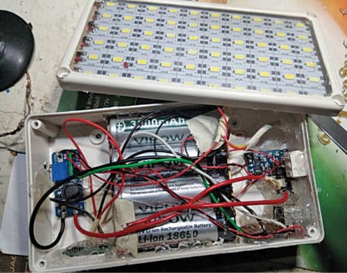
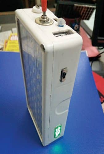
The power bank with 12Ah can deliver 2A current for charging a mobile phone. There is a provision for adjusting the charging rate through boost converter module. Also, there is a digital voltmeter that monitors Li-ion rechargeable battery pack’s voltage as well as the mobile charging voltage. Inside view of the author’s prototype is shown in Fig. 1.
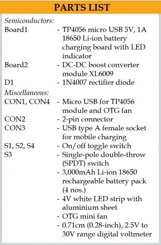
Following components would be required to build the project:

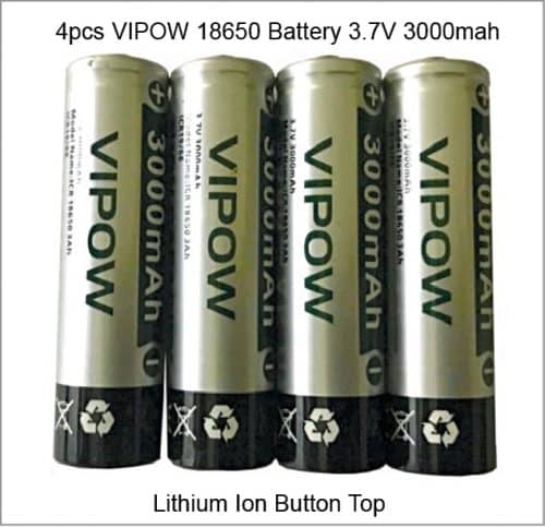
- Four 3,000mAh Li-ion 18650 type batteries (see Fig. 3)
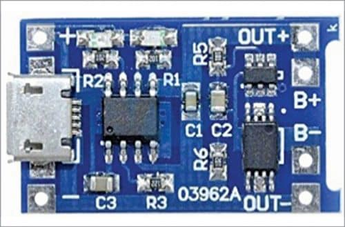
- A 5V, 1A TP4056 micro USB battery charger module with inbuilt LED indicator for charging and automatic overcharge protection system
- A 4V white LED strip with aluminium-sheet base
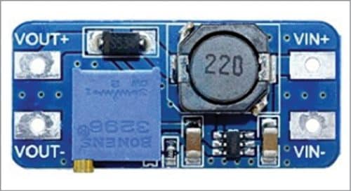
- An XL6009 DC-DC boost converter module
- Two SPST switches
- One SPDT switch for the digital voltmeter
- A tiny 0.71cm (0.28-inch), 2.5V to 30V DC range mini digital voltmeter
- Switchboard’s plastic enclosure with USB female sockets for mobile charging and OTG fan
- Transparent acrylic sheet for the emergency light on the front side
- An OTG mini fan
Circuit and working
The circuit diagram of the emergency light with power bank and OTG fan driver is shown in Fig. 2. It is built around TP4056 charging module (Board1), DC-DC booster module (Board2), four 18650 type Li-ion batteries (BATT.1), 6 x 10 LED-array, and a few other components.
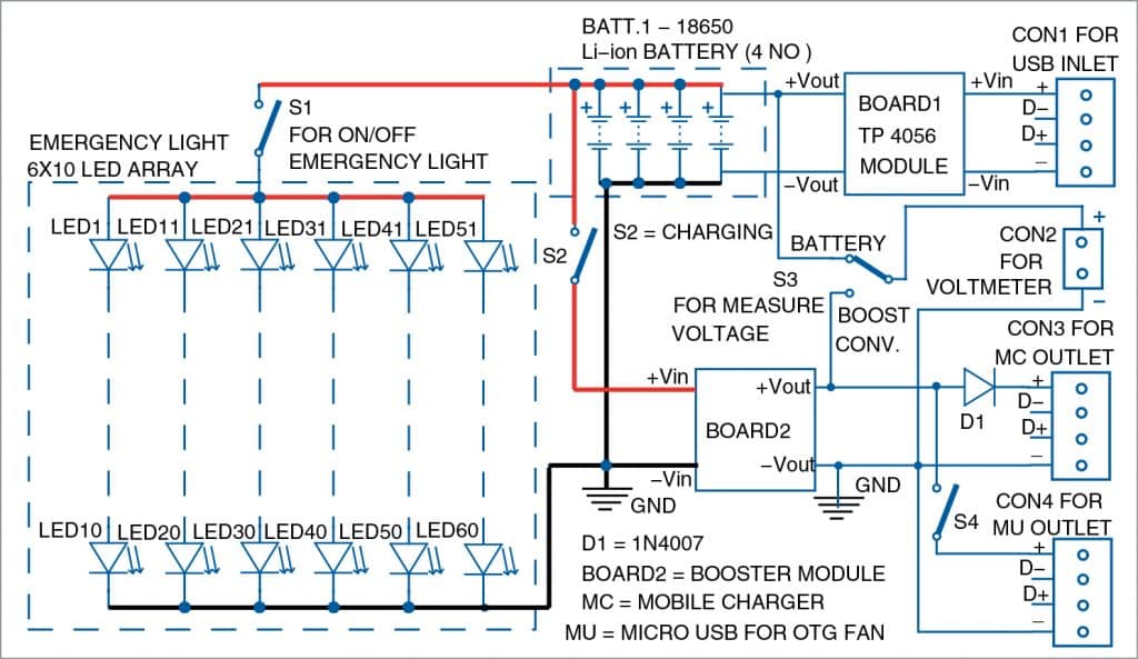
TP4056 charging module used in the project is shown in Fig. 4 and XL6009 DC-DC booster module in Fig. 5.
Battery bank charger
The battery bank includes four Li-ion 18650 type cells that are connected in parallel. For charging the Li-ion battery bank, a TP4056 charging board (5V, 1A) with an LED indicator and automatic protection is used. Only one charging module is used in this project.
With a good quality smartphone charger input at CON1, it takes around two hours to fully charge the battery bank. When it is fully charged (battery voltage is 4.1 volts), the inbuilt red LED of TP4056 module becomes green. Though maximum voltage of Li-ion battery is 4.2 volts but, for safety reasons, charging stops at 4.1 volts.
The power bank’s output can be used to drive an emergency light, charge a mobile phone, or drive a mini OTG DC fan (refer Fig. 6). For emergency light, six 4-volt strips, with ten LEDs on each strip, are used in parallel. Switch S1 is used to switch the emergency light on/off.

XL6009 booster module
When the power bank’s output is connected to a load such as an emergency light, its battery voltage slowly starts dropping. To maintain a constant voltage level for charging a mobile phone or driving a mini fan, an XL6009 DC-DC step-up converter module is used (via switch S2). It is basically an adjustable power booster module that raises the power bank’s output (low battery voltage) from 4.1 volts to 5 volts.
Using XL6009’s inbuilt trimmer, its output voltage can be increased to 5.5 volts for quick charging of a smartphone. But this voltage needs to be limited to 5.5 volts and should not be increased beyond this level for safety of the connected device. Recommended set point of output voltage is 5V.
The output is available through a standard female USB socket for charging mobile phones using a USB cable. This mobile charging output is available at CON3 in the circuit.
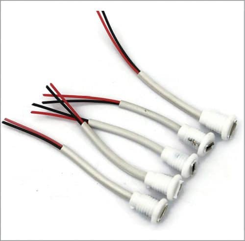
Another micro USB female socket is used at CON4 for driving the OTG mini fan. Switch S4 is used to switch off OTG fan. Typical female USB sockets available in the market are shown in Fig. 7.
A mini digital voltmeter is used to show the battery bank’s voltage and boost converter’s output voltage to monitor the power bank’s condition and mobile phone’s charging state. A single-pole, double-throw (SPDT) switch (S3) is used to select between the power bank output and mobile charging output voltages.
Construction
A 17.78×10.16×3.81cm (7×4×1.5-inch) size plastic box can be used for housing the entire circuitry. It can accommodate all the components including Li-ion battery bank and LED lights.
The slots for switches and USB sockets can be provided on the enclosure as shown in Fig. 8. You may use a small knife or a poker to make holes in the plastic box for the sockets and switches and fix them using hot glue and double-sided tape.
A transparent acrylic sheet can be used on the front side for covering the LEDs of emergency light. Since aluminium sheet is present at the back of each LED strip, no separate heat-sink is required.
The author’s finished prototype for the emergency light is shown in Fig. 8.
Gautam Kumar Mandal is deputy general manager in Durgapur Steel Plant (SAIL). He did his M. Tech from NIT, Durgapur and B.E. from BE College, Shibpur (now IIEST-Shibpur). He is an electronics hobbyist and a regular reader and contributor to EFY.

It is a very suitable tool for Mountain climbers
Thanks for the feedback!