


 There are many types of home and industrial automation systems available in the market. These include IR remote controller, Bluetooth home automation, DTMF home automation, Wi-Fi home automation, RF home automation, and voice controlled home automation. The one presented here is a low-cost automation system. It can be used at home or in an industrial environment to switch devices on and off.
IR remote controllers and receivers follow standard protocols for sending and receiving the data. Some of the standard protocols are NEC, PHILIPS RC5, JVC, and SIRC (Sony infrared remote control). We will be using the NEC protocol for this project. After understanding the frame format of IR remote, we will interface IR receiver TSOP1738 with PIC16F676 microcontroller to decode the key pressed from an NEC IR remote, as shown in Fig. 1.


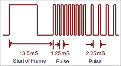
Each bit is transmitted using the pulse distance, as shown in Fig. 2. Logical ‘0’ is a 562.5µs pulse burst followed by a 562.5µs space, with a total transmit time of 1.125ms. Logical ‘1’ is a 562.5µs pulse burst followed by a 1.6875ms space, with a total transmit time of 2.25ms.
When a key is pressed on the remote controller, the message transmitted consists of the following in the order below:
- A 9ms leading pulse burst (16 times the pulse burst length used for a logical data bit)
- A 4.5ms space
- The 8-bit address for the receiving device
- The 8-bit logical inverse of the address
- The 8-bit command
- The 8-bit logical inverse of the command
- A final 562.5µs pulse burst to signify the end of message transmission
The four bytes of data bits each are sent with least significant bit first. Fig. 3 illustrates the format of an NEC IR transmission frame for an address of 00h (00000000b) and a command of ADh (10101101b).
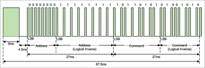
A total of 67.5ms is required to transmit a message frame. It needs 27ms to transmit the 16 bits of address (address+inverse) and the 16 bits of command (command+ inverse).
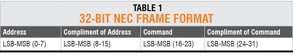
Table 1 shows 32-bit NEC frame format and Table 2 shows the complete list of IR key codes for the NEC IR remote.
 PIC16F676 controller
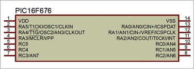
PIC16F676 is Microchip’s 8-bit CMOS PIC microcontroller with flash memory. It comes in a 14-pin package with high-performance RISC CPU, which makes it an ideal choice for most electronic applications related to embedded systems or industrial automation. This tiny chip incorporates everything you need to develop individual projects. Some of its features are:
- The flash memory of high-performance PIC16F676 helps in increasing the processing speed of the microcontroller.
- It comes in PDIP, SOIC, and TSOP packages, all of which are available in 14-pin configuration.
- PIC16F676 contains program memory with memory space around 1.7kB, while RAM and EEPROM memories are of 64 bytes and 128 bytes, respectively.
- One 10-bit ADC module in the device comes with eight analogue channels. This module plays a vital role for sensor interfacing and converting analogue values to digital.
- Power-on reset, comparator, in-circuit serial programming, and master clear reset are some other features incorporated in the device. These help it stay ahead of the other onboard chips and removes the need of buying external components for carrying out different operations. Pin diagram of PIC16F676 is shown in Fig. 4.
Circuit and working
The project uses PIC16F676 microcontroller and an NEC IR remote to switch on/off any AC load, including lights and fans, from the comfort of your chair or bed. The different IR signals from the remote for the different lights and fans are received by the microcontroller, which then controls the respective relays via a relay driver circuit. These relays are used to switch the lights and fans on or off.
 There are many types of IR remote controllers available for different devices, but most of them work around 38kHz frequency. This project requires an ordinary IR TV remote. For detecting the IR signals, TSOP 1738 IR receiver shown in
Fig. 5 is used. It can sense the 38kHz frequency signal.

The block diagram of the project is shown in Fig. 6.
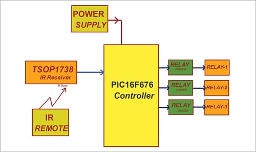
In this project the digital IO pins RC0, RC1, and RC2 of Port C of PIC16F676 microcontroller are used to control the relays to switch the appliances on/off. These pins are configured as output pins in the program. The IR receiver is connected to pin RC4 of PIC16F676, which is configured as input pin in the program.
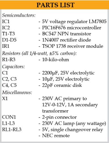
The PIC16F676 microcontroller operates at +5V. Hence, a transformer is used to step down the 230V AC mains supply, which is rectified using a full-wave rectifier. The rectified voltage is regulated to +5V by using regulator IC 7805. The complete circuit diagram is shown in Fig. 7.
The working of this project is fairly simple. When a button is pressed on the IR remote, it sends a sequence of codes in the form of encoded pulses using 38kHz modulating frequency. These pulses are received by the TSOP 1738 sensor and then read by the microcontroller. The microcontroller decodes the received train of the pulses into a hex value and compares it with the predefined hex values in the program.
Whenever a key is pressed on the IR remote, the transmitted IR signal is received by an IR receiver and the key is decoded by the software. In this project, the entire 32-bit string (4 bytes of NEC protocol) is used for decoding. In this 32-bit string, the third byte is compared in the program for controlling the lights/fans. If any match occurs, the controller performs a relative operation by triggering the respective relay through transistor BC547 and the corresponding result is indicated by an on-board LED. The three LEDs in the circuit show the status of the relays.
In this project, key numbers 2, 4, and 6 of the IR remote have been used for controlling the three relays. Key 2 toggles relay RL1, key 4 toggles relay RL2, and key 6 toggles relay RL3.
Software
The circuit uses the software program loaded into the internal memory of PIC16F676. The program is compiled using Mikro C PRO version 7.2.0 for PIC compiler and uploaded into PIC16F676. The software main.c is written in embedded C language, which allows writing the code within a few lines. The generated hex code is burnt into the MCU chip using PIC K150 programmer board.
No header, interrupt, or capture and compare mode is used here to detect IR signal. Digital pin RC4 reads the data, just like we read a push button. Whenever signal goes high or low, debouncing is adopted and the timer is run. Whenever the pin changes its state to another, the time values are saved in an array.
IR remote sends logic 0 as 562.5µs pulse and logic 1 as 2250µs pulse. Whenever timer detects 562.5µs pulse, the program assumes it to be 0, and when it detects 2250µs pulse, it assumes it to be 1. Then the program converts it into hex. The incoming signal from remote contains 32 bits (4 bytes). Program stores all the bytes in the array and then decodes the third byte to use for comparison.
The simple programming statement ‘switch’ case is used to detect and control the home appliances.
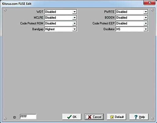
Do not forget to set fuse bits before programming PIC16F676 using PIC K150 programmer. The program will not work without setting the fuse bits. The fuse bit settings are shown in Fig. 8.
Construction and testing
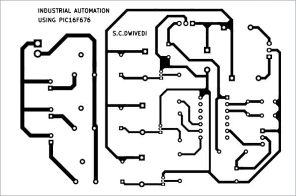
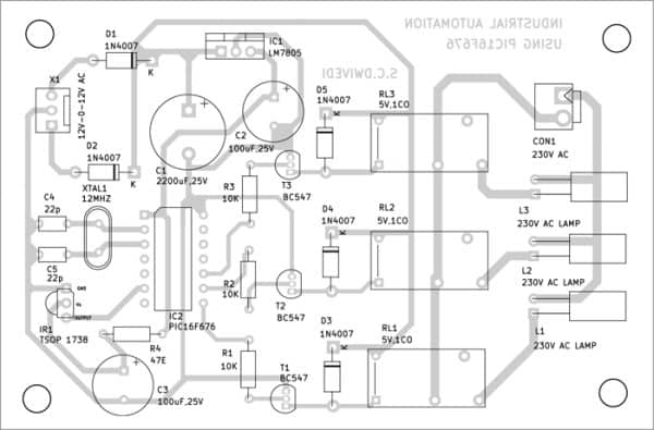
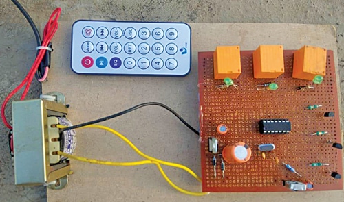
An actual-size PCB layout for the automation system is shown in Fig. 9 and its component layout in Fig. 10. After assembling the circuit on PCB, enclose it in a suitable box. Receiver IR1 should be fixed on the front panel, so that the remote can focus on it to activate any load connected to the respective relay. CON1 should be fixed on back side of the cabinet. All the three 230V AC appliances are connected to the circuit using two wires and placed at their location. The author’s prototype wired on a general-purpose PCB is shown in Fig. 11.
Download PCB and Component Layout PDFs: click here
Download Source Code
Pamarthi Kanakaraja is an assistant professor (R&D cell) at K.L. University, Vaddeswaram, Guntur district, Andhra Pradesh