This multi-purpose security system utilises wire loops to secure items. Wire loops can be employed in various ways for security applications such as luggage security, bike security, bicycle security, room security, and door security. A wire loop, when attached to security items and alarm mechanisms, detects and alerts in case of unauthorised attempts to tamper with the wire loop.
Use a thin, flexible, and durable conductive wire to create a loop around the area you want to secure. Install the wire loop around the desired perimeter, whether it be a doorway, window, or any other access point. When a breach is detected (e.g., someone cuts or breaks the wire loop), the alarm system activates.
POC Videos In English
| Parts List | |
| Semiconductors: | |
| IC1 | -UM66 melody generator |
| IC2 | -LM386 low power amplifier |
| T1 | -BC327 pnp transistor |
| ZD1 | -3.1V zener diode |
| LED1 | -5mm LED |
| Resistors (all 1/4-watt, ±5% carbon): | |
| R1 | -1-kilo-ohm |
| R2 | -10-kilo-ohm |
| R3 | -220-ohm |
| Capacitors: | |
| C1 | -470μF, 25V electrolytic |
| C2 | -10μF, 25V electrolytic |
| C3 | -220μF, 25V electrolytic |
| Miscellaneous: | |
| JACK1 | -DC socket |
| S1 | -SPDT switch |
| CON1 | -2-pin connector |
| Batt.1 | -9V battery |
| LS1 | -8-ohm, 0.5-watt speaker |
| -9V DC adaptor | |
| -Flexible wire for loop (length as per requirement) | |
Circuit and working
The circuit diagram of the multi-purpose security system is shown in Fig. 2. It is built around transistor BC327 (T1), melody generator UM66 (IC1), low-power audio amplifier LM386 (IC2), 8-ohm half-watt loudspeaker (LS1), 9V battery or 9V adaptor, and a few other components. Around one metre of flexible wire is used as a sensor, forming a loop to connect the article (such as luggage) to CON1 in the circuit.


The melody signal produced by the UM66 melody generator is weak. To amplify the sound signals, the widely-used audio amplifier LM386 is employed.
To understand the working of the circuit, first comprehend the pin descriptions of LM386. Pins 1 and 8 are used for gaining control of the amplifier. Pins 2 and 3 feed the input signal for amplification, with pin 2 for negative input and pin 3 for positive signal. Pin 4 is used for ground, while pin 6 is used for the positive 9V DC power supply. Pin 5 is the output, connected to a loudspeaker through a capacitor. Pin 7 is not utilised in this configuration.

The system’s operation is straightforward. When power is supplied via a battery or adaptor, the musical IC UM66 (IC1) gets activated and begins producing musical sound at its output pin 3. The speaker can be directly attached between pin 3 and ground of IC1 to hear the musical sound. For louder sound, LM386 is used. The 3.1V zener diode ZD1 is connected at pin 2 of IC1 to protect it from voltage beyond 3.1V.
To amplify the signals, adjust the gain factor through pins 1 and 8. If left open, the gain will be 20dB, as internally set in the IC. By adding a 10µF capacitor (C2) between pins 1 and 8, the gain can be varied up to 200dB. Feed the required signals to pin 3 of IC2.
The musical signal output from IC1 is connected to pin 3 to obtain amplified output on pin 5 of IC2. Capacitor C3 acts as a coupling capacitor, removing DC signals and passing audio signals through it. The amplified signals are then output through speaker LS1.
First, connect a flexible wire as a loop between CON1 and the article (such as luggage) to be protected. The system operates with either a 9V battery or 9V adaptor, depending on the application. After connecting a battery, switch S1 probe towards the battery side. If LED1 glows, the system is ready to use.
After using the power source, keep the mode switch towards the source used. Now, 9V is available in the system. When someone breaks the loop, transistor T1 starts conducting and IC1 receives 3.1V to activate it.
In this system, a flexible wire loop is interfaced as a sensor with the musical IC UM66. LED1 is used in the system as a power supply indicator.
The flexible wire has two terminals which need to be connected across CON1 via the item during security measures. When the loop is cut or broken, it provides a low voltage at the base of transistor T1. Transistor T1 then conducts, enabling IC1 to activate the melody generator sound. The output of IC1 is further directed to IC2 for louder sound.
Construction and testing
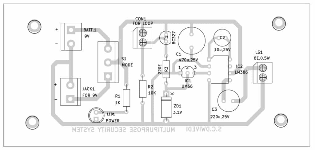
A single-side PCB layout for the musical security alarm is shown in Fig. 3, with its component layout displayed in Fig. 4.

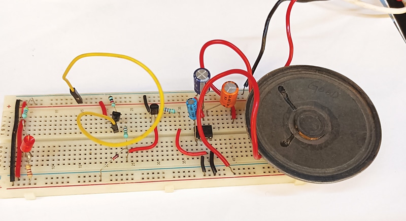
After assembling the circuit on the PCB, enclose it in a suitable box. Fix LED1 and CON1 on the front side of the box, and the mains power connector JACK1 and 9V battery on the rear side. Connect the flexible wire loop between points A and B (refer to CON1 in Fig. 1) via the item to be secured, ensuring that the loop would break easily when someone attempts to tamper with it.
Bonus. You can watch the video of the tutorial of this DIY project at https://www.electronicsforu.com/videos-slideshows/make-multipurpose-security-system
S.C. Dwivedi is an electronics enthusiast and circuit designer at EFY