


 This simple security alarm circuit can help you secure your bike or scooter. It raises an alarm if someone tries to drive away your two-wheeler. You just need to connect the circuit to the vehicle’s wheel (preferably front wheel) through a thin flexible wire that can break easily.
Connect the bike’s wheel to the circuit with the wire in such a way that when someone tries to steal the bike, the wire would break. When that happens, the speaker in the circuit would generate a machine-gun sound, or some other alarming sound, and alert everyone around.
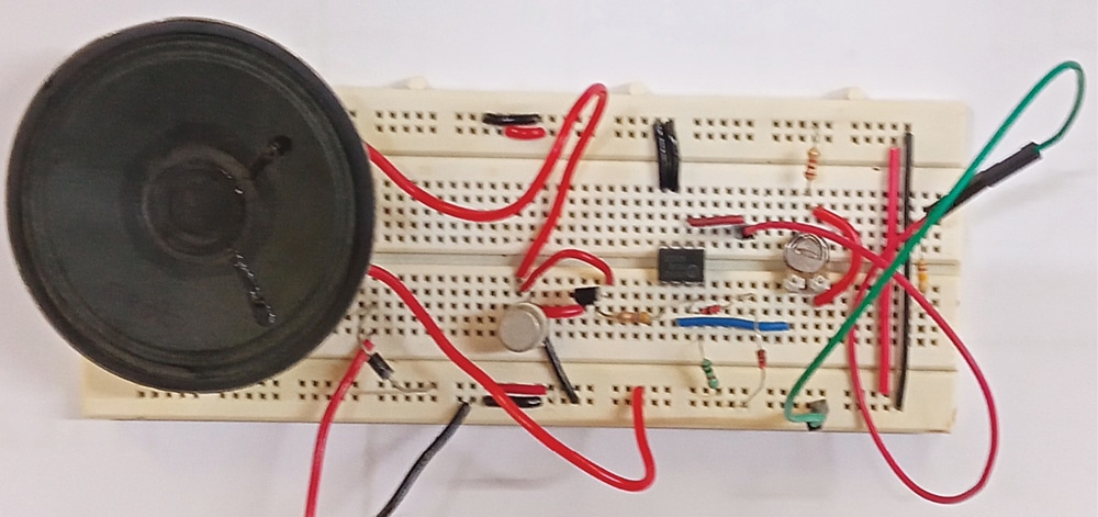
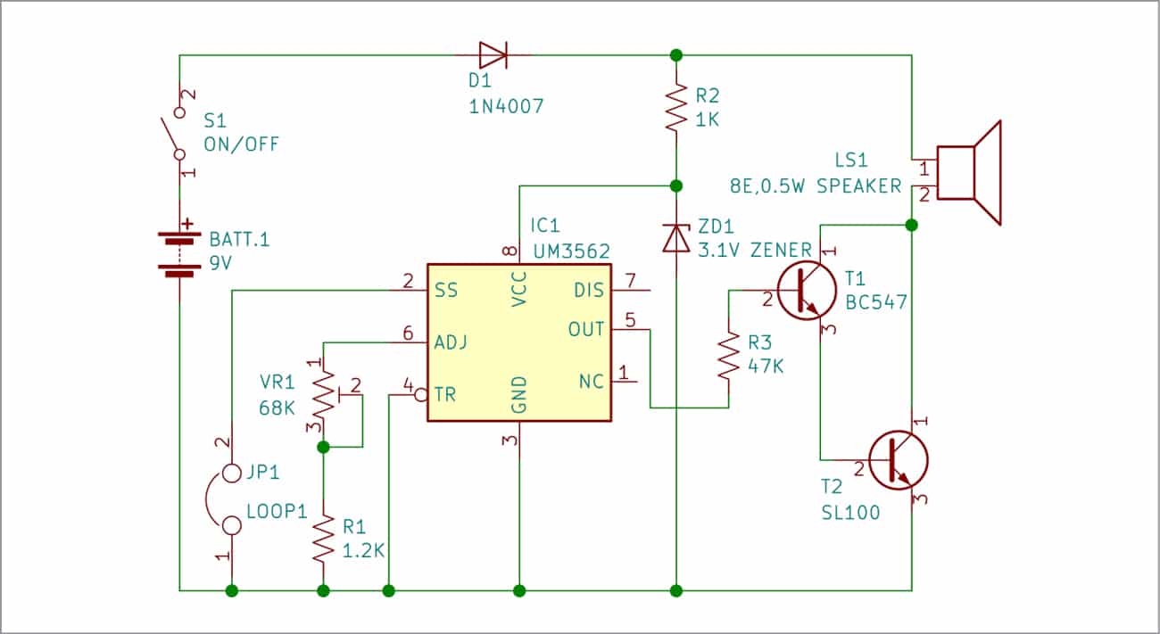
The prototype assembled on a breadboard for testing in EFY Lab is shown in Fig. 1. Circuit diagram of the security alarm is shown in Fig. 2.

Video Tutorial:
Circuit and working
The alarm circuit is built around machine-gun sound generator IC UM3562 (IC1), transistors BC547 (T1) and SL100 (T2), a 3.1V Zener diode (ZD1), rectifier diode 1N4007 (D1), and a loudspeaker (LS1).
Sound generator IC UM3562, the heart of the circuit, is a low-power CMOS LSI (large-scale integration) chip in an 8-pin DIP package. It includes a voltage-controlled oscillator (VCO), timer generator, tristate selector switch, envelop control, and mixer.
Normally pin 2 of UM3562, along with trigger pin 4, is used as a tri-state selector switch that helps generate three types of sound. When pin 2 is low, a special kind of pulsating sound is generated. When it is connected to 3V, it generates a rifle’s firing sound. When this pin is in floating condition (unconnected), it generates the machine-gun sound.
In this design, pin 2 is kept in low state by making trigger pin 4’s state low. When the wire connecting the circuit to vehicle’s wheel breaks, machine-gun sound is generated. The machine-gun’s shooting rate (sound) can be adjusted through preset VR1.
IC UM3562 works on 2.4 to 3.6V, so normally it uses a 3V battery for operation. In this circuit, 9V battery voltage is reduced to the required level by R2 and ZD1. The 9V battery helps in producing a louder alarm sound from loudspeaker LS1.
Output of the UM3562 at pin 5 is in audio range. The two transistors T1 and T2 used as a Darlington pair amplify the sound.
Working of the circuit is simple. After connecting the circuit to bike’s wheel, switch on S1 to enable the circuit. This readies the circuit to protect the bike. When someone tries to drive away the bike and breaks the wire, loudspeaker LS1 sounds an alert to let you know someone is trying to steal your bike.
| Parts List | |
| Semiconductors: | |
| IC1 | – UM3562 machine-gun sound generator |
| T1 | – BC547 NPN transistor |
| T2 | – SL100 NPN transistor |
| D1 | – 1N4007 rectifier diode |
| ZD1 | – 3.1V Zener diode |
| Resistors (all 1/4-watt, ±5% carbon), unless stated otherwise: | |
| R1 | – 1.2-kilo-ohm |
| R2 | – 1-kilo-ohm |
| R3 | – 47-kilo-ohm |
| VR1 | – 68-kilo-ohm preset |
| Miscellaneous: | |
| S1 | – On/off switch |
| LS1 | – 8-ohm, 0.5-watt speaker |
| BATT.1 | – 9V battery |
| – Thin flexible wire | |
Construction and testing
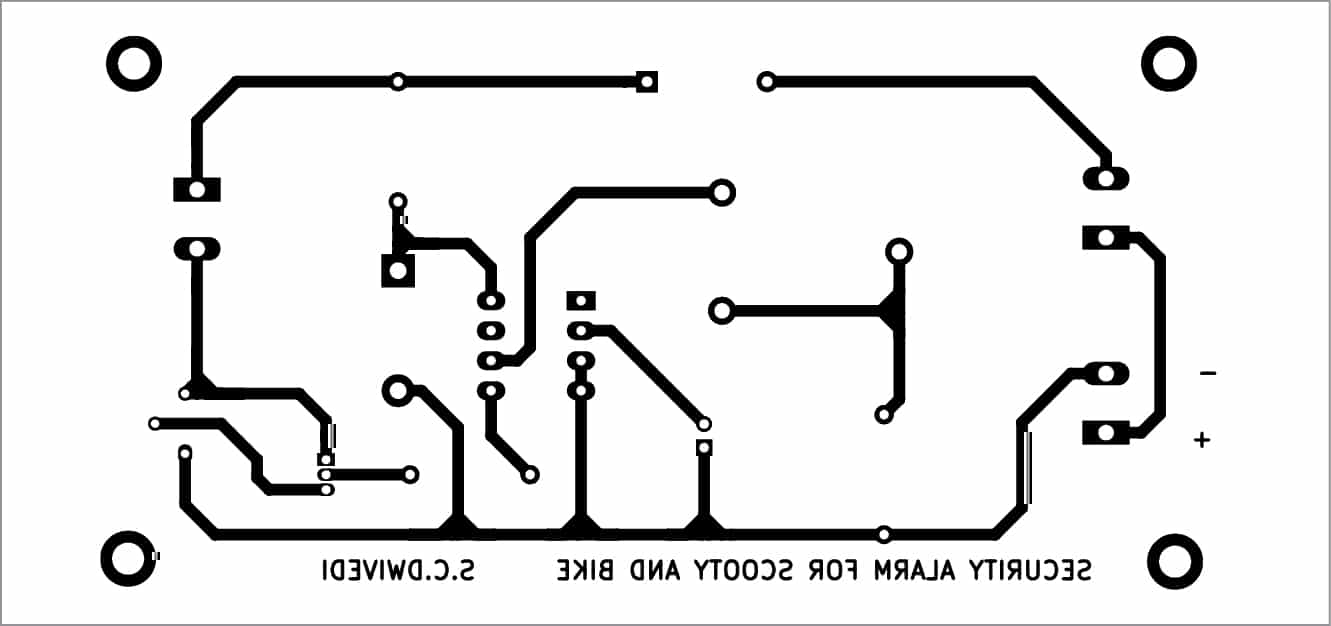
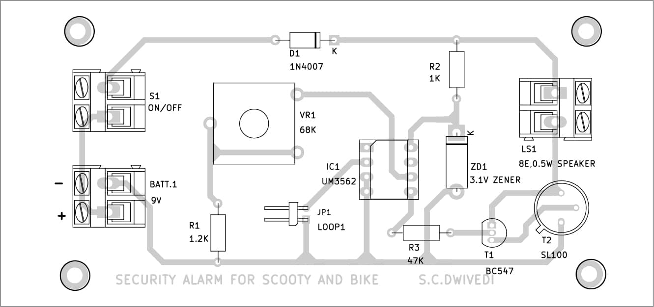
A single-side PCB for the bike alarm is shown in Fig. 3 and its component layout in Fig. 4. After assembling the circuit on PCB, enclose it in a suitable box. Connect the flexible wire tightly to the bike’s wheel such that it would break if someone turns the bike’s handle to drive it away.
Download PCB and Component Layout PDFs: click here
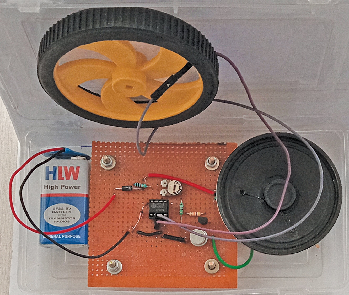
After connecting battery to the circuit, switch on S1 and hide the assembled unit somewhere in the bike (say, under the spare tyre). Fix the thin flexible wire in such a way that it will definitely break when someone turns the vehicle’s handle to move it. The author’s prototype wired on a general-purpose PCB and fitted in a plastic box is shown in
Fig. 5.
BONUS. You can watch the VIDEO of the tutorial of this DIY project at: https://www.electronicsforu.com/videos-slideshows/live-diy-security-alarm-scooty-bike
S.C. Dwivedi is an electronics enthusiast and circuit designer at EFY
