


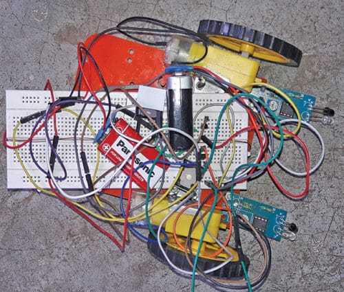
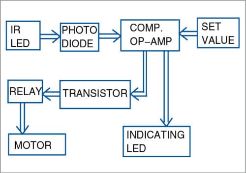
 Presented here is the design for a relay-based line follower robot without using a microcontroller (MCU). The robot provides a simple application to get started with sensor-based projects for newbie electronic hobbyists and enthusiasts. It can follow a black line/track (on white surface) or a white line/track (on black surface). The authors’ prototype of the robot is shown in Fig. 1. Block diagram of the project is shown in Fig. 2.
Circuit and working
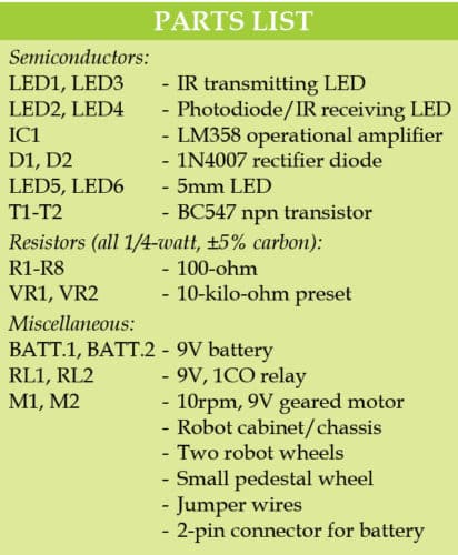
The circuit diagram of the line follower robot is shown in Fig. 3. It is built around infrared (IR) TX LEDs (LED1 and LED3), two IR RX photodiodes (LED2 and LED4), dual-operational amplifier LM358 (IC1), two rectifier 1N4007 diodes (D1 and D2), two LEDs (LED5 and LED6), two single-changeover relays (RL1 and RL2), two 10rpm geared motors and a few other components, including two wheels and a cabinet.

Sensor
Two pairs of IR transmitter (IR TX) and IR receiver (IR RX) sensors are used. When a surface is detected by IR LED, IR rays emitted by IR TX are reflected onto photodiode IR RX, which turns on the photodiode in conducting state. Signals from IR RXs are fed to non-inverting inputs of LM358.

Comparator
LM358 operational amplifier (IC1) is used as a comparator that acts as an analogue signal processor. The comparator can be considered a binary output device, since it provides only two values/states of output in volts: +Vcc and 0V.
In this project, if V1 and V2 are the voltages applied to non-inverting and inverting input terminals, respectively, of LM358, then output of comparator Vout=+Vcc, if V1>V2, otherwise Vout=0V
Transistors
Bipolar junction transistors (BJTs) are used as relay drivers. Outputs OUT1 and OUT2 of IC1 are connected to the bases of transistors T1 and T2 through resistors R5 and R8, respectively. Here, each transistor is used as a switch to drive the corresponding relay.
Fig. 4 shows the prototype module with the sensor and LM358 used in this project. VCC, gnd and output terminals are shown in the module.

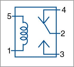
Relay
Pin diagram of the relay is shown in Fig. 5. When current flows through the coil of the relay from pins 5 to 1, it results in short-circuit between pins 3 and 2. However, pins 2 and 4 of the relay are shorted if no energising current is passed through the coil. A diode is connected in reverse-biased mode across the relay for protection.
White surface
For white surface, output of the comparator connected to IR sensor is high, because IR ray reflects on a white surface. Output of the comparator drives the transistor and, hence, transistor conducts and current flows through the relay coil and the relay is energised.
Black surface
Output of the comparator connected to IR sensor is low (0V) for a black surface. The transistor does not conduct and no current flows through the relay coil. Thus, relay is in de-energised state.
Black line follower robot
The circuit diagram of the black line follower robot is shown in Fig. 3. When the right side of the robot is on the white surface, the right motor is activated. When the left side of robot is on the black surface, the left motor is inactive. Hence, the robot turns left.
When the right side of the robot is on the black surface, the right motor is inactive. When the left side of the robot is on the white surface, the left motor is activated. So, the robot turns right.
When both sides are on the white surface, both motors are activated. And, the robot goes straight.
White line follower robot
The circuit diagram of the white line follower robot is the same, except the changing NO and NC contacts of the relay. When the relay is de-energised, pins 4 and 2 of the relay (Fig. 5) are shorted. Hence, current flows through the motor.
When the right side of robot is on the white surface, the right motor is inactive. When the left side of the robot is on the black surface, the left motor is activated. So, the robot turns right.
When the right side of robot is on the black surface, the right motor is activated. When the left side of the robot is on the white surface, the left motor is inactive. So, the robot turns left.
When both sides are on the black surface, both motors are activated. Hence, the robot follows a straight line.
Construction and testing
A PCB layout of the relay-based line follower is shown in Fig. 6 and its components layout in Fig. 7. After assembling the circuit on the PCB, connect 9V battery to BATT.1 and BATT.2. Use jumper wires to connect IR TXs and photodiodes IR RXs. Place these properly on the chassis of the robot.

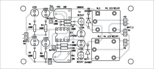
Download PCB and component layout PDFs: click here
When you keep the robot on the floor, reflected rays from IR TXs should fall on photodiode IR RXs. Align the sensor pairs (IR TX and IR RX) in such a way that the robot follows the prefix black or white line.
Souvik Kumar Das is passionate about electronics and MCU-based system design.
Shibendu Mahata is M.Tech (gold medalist) in instrumentation and electronics engineering from Jadavpur University. His interests include designing MCU-based real-time embedded signal processing and process control systems.
I dont understand as to what u intend in showing a photo of ready made module and a circuit diagram with different values of resistances. I bought a pair of sensors from “Amazon” and it uses lm393 instead oflm358. The out put when sensed is “0”volt otherwise it shows vcc itself. Also there is another project on the next page(78) of october2018 issue which uses “sharp2y0A21″sensor.
Request some help as to how can I use the purchased sensor in either project.
The author Shibendu Mahata replies:
1. LM358 is a dual, differential-input op-amp, while, LM393 is a dual comparator IC. For the application shown in our article, LM393 can also be used instead of LM358.
2. Since our project is line-tracking/following, the reader may try to use the “sharp2y0A21″sensor for obstacle detection as well as distance measurement applications. Since the joy of learning electronics is through self-discovery, the reader should try to explore other possibilities as well on his own.