 As seen in James Bond movies, audio spy bugging devices are used by intelligence agents in different parts of the world. These devices can help hear conversations from a distance. Their size is extremely small which helps them fit into a pocket and even inside a pen.
Similarly, we designed an FM audio bug spy device whose range is up to 1km(or even more). The audio is both transmitted and received via frequency modulation.
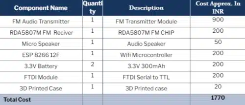
The components listed in the bill of materials table below are needed for this project.
Bill of Materials
FM Spy Bug Transmitter
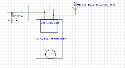
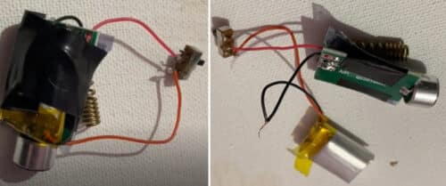
The audio transmitter used here has a mic and 3 pins as seen in the above circuit. The Vcc and GND pins are connected to a 3.3V rechargeable battery that powers the transmitter module. The third pin is to connect the antenna for the transmitting range to be extended.
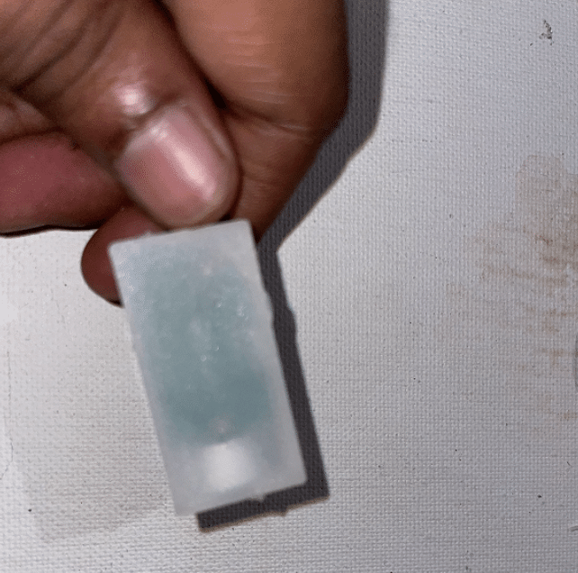
The case that is being used to place the transmitter in, needs to have tiny holes, such that the mic can capture the sound. In this project, we have used a 3D-printed case by designing it accordingly.
Audio Spy Bug Receiver
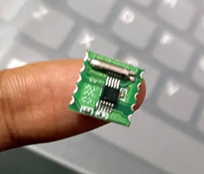
The RDA5807M frequency modulation chip is as tiny as shown below. An ESP8266 12F chip is needed to drive it; as it works on I2C communication which is the same interface used with the ESP chip. This scans and matches the frequency of the receiver with the transmitted signal.
Since the ESP8266 chip does not have USB ports, an FTDI module is needed to program it for communication. Using the USART serial port to drive the RDA5807M FM chip, we send the command to ESP which further sends the signal to the I2C port of the FM chip.
To create the program, the radio library is used to drive the FM chip and to be used over I2C. The ESP board in the Arduino IDE needs to be installed, after which the library and programming of the ESP chip can be done.
After installing the radio library in the Arduino IDE, Go to Examples and upload the scan code to the ESP chip.
The ESP chip has to be set in the programming mode by connecting the GPIO 0 to GND and Vcc to 3V of the FTDI module. The GND to GND has to be connected along with the Tx pin to the Rx pin and vice versa before uploading the code.
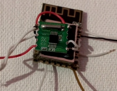
FM Audio Bug Circuit Connections
After the ESP chip is programmed, the modules should be connected. From the circuit diagram, it is seen that the FM audio transmitter module is connected to the battery inside the case as designed in the pic below.
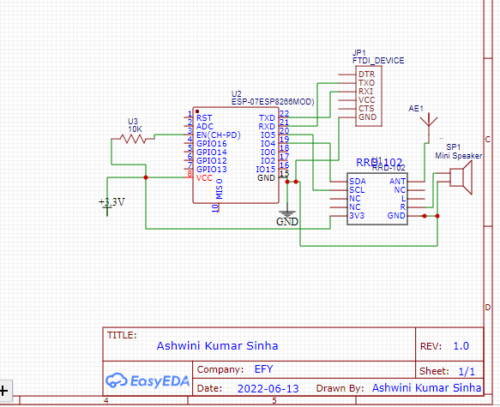
Next, the ESP and RDA5807M transmitter chip wires are soldered accordingly. The I2C pins of the RDA5807M chip are soldered with ESP 12F I2C pins. The powering pins are soldered to 3V and Vcc pins of ESP, apart from the GND to GND pins.
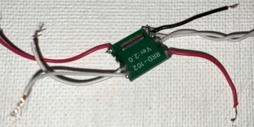
The antenna is now connected to the FM ANT pin of RDA5807M. Two microsized speakers are connected to the RDA5807M L & R audio pins.
After all this, we fit it inside the enclosure.
Programming Audio Spy Bug Device
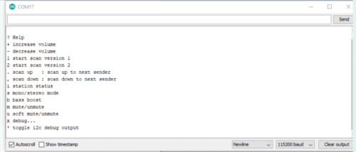

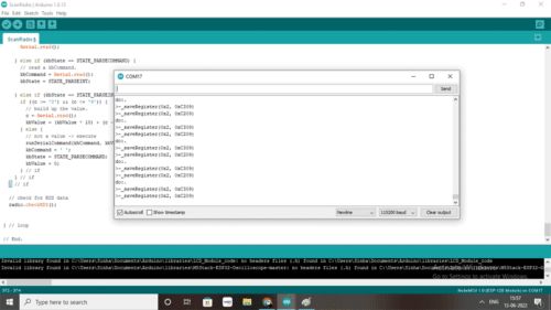
Download FM Audio Bug Spy Device Source Code
The audio transmitter FM device is powered-on and hidden in the desired location. The ESP and FM radio receiver device are plugged and the serial port is opened. After scanning the range of FM channels, the channel for the right frequency is selected.
In other words, this means, the FM channel of the audio bugging device is selected, and you can now hear what is being talked about at the place the transmitter is placed.
So now you know how to make FM Bug Device at home. Still, if you face any issues or have any questions, please ask in the comments below.
You can also check our previous DIY audio bug device using GSM Module and Arduino.
Also, you can start conversations with DIYers, electronics hobbyists, and experts using our Forum.
This article is published on 22 July 2022. Recently updated on 10 October 2022


Sir,can you please provide the SOURCE CODE for
Small fm transmitter audio bug spy device.
Code is added at end of article
Hi Ashwini I wanna implement the Continuity Tester With A Chirping Sound in our organization of auto components where rejection rate is high in VMC drilling process, I have link of that tester but not able to understand electronics, I wanna ur email & phone so that I can invite u in our organization for help, Surely we will seat with our MD for implementing this project. Pls support
https://www.electronicsforu.com/electronics-projects/continuity-tester-chirping-sound#comment-343792
Sure will try to help if I can. You can contact on my whats app with more details 7061350809
what are the difficulties faced while doing this project?
CAN I HAVE THE WORKING PRINCIPLE