 Designing wireless charging systems for small-size electronic devices like smartwatches, AirPods, Bluetooth headsets, etc. is very difficult. Added to that only a few types of these devices support wireless charging.
While none of the earphones today can be charged wirelessly, a charging case is provided for both charging and storing the earphones. On the other hand, wireless charging technology is growing with new designs. Few of these designs can even charge devices up to a distance of a meter.You can charge while it is not physically connected to any charger it charging over the air using the electromagnetic waves same technology is can be applied even for these small-sized electronic devices . However, the drawback is that very few(sometimes none) of these devices can actually be wirelessly charged. Like earbuds and AirPods are not capable of a wireless charging system and we can not use the benefit of this amazing over the air truly wireless charging system so, I have decided why not let’s do some experiments and try to make a basic circuit that helps us to enable this design a wireless charging even in smallest wearable AirPods.
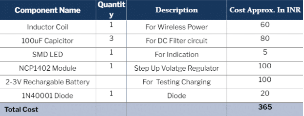
This DIY is a basic circuit that helps us design a wireless charging system. A very small coil (inductor with an IC) is used. This circuit can fit in earphones for wireless charging and is able to fit in wearable watches and other wearable devices and small IOT devices and help them to charge wirelessly. The following components are needed for this circuit.

Bill Of Material
Connection
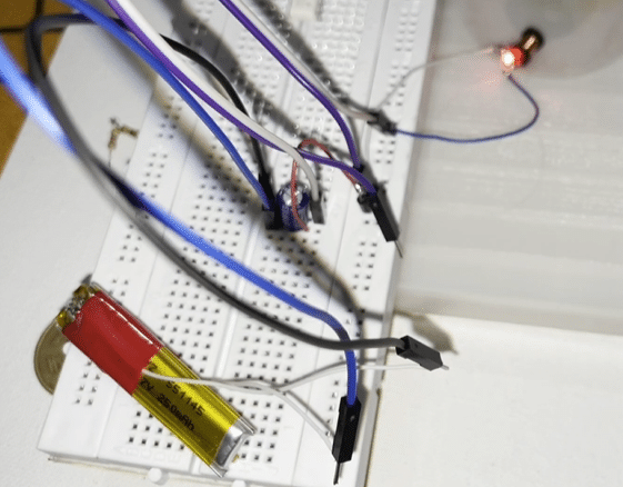
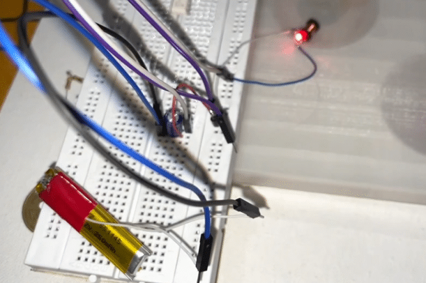
The size of the circuit is kept as small as possible. Many experiments with wires and coils were conducted, when suddenly the idea of connecting an inductor coil with LED struck. So, technically as per mutual induction theory the coil will induce electricity when placed in an electromagnetic flux and the LED will glow. So this circuit is placed near the wireless charger and the inductor induced EMF makes the LED glow as shown in figure 2. The inductor is so small (3mm), that it can fit in our wearable electronic devices’ charging circuit. A circuit that filters the current and generates less noise DC current is added. Next, the voltage has to be stepped up and regulated to 3V or 5V to power the device wirelessly. Hence the NCP 1402 is added to the circuit.
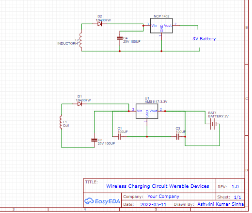
The components have to be connected as shown in the circuit diagram(figure 3). The first circuit diagram in the figure is for charging a 1-2V battery that has a voltage regulator of 3.3V; and the second is for charging a 3V battery that has a 5V regulator.
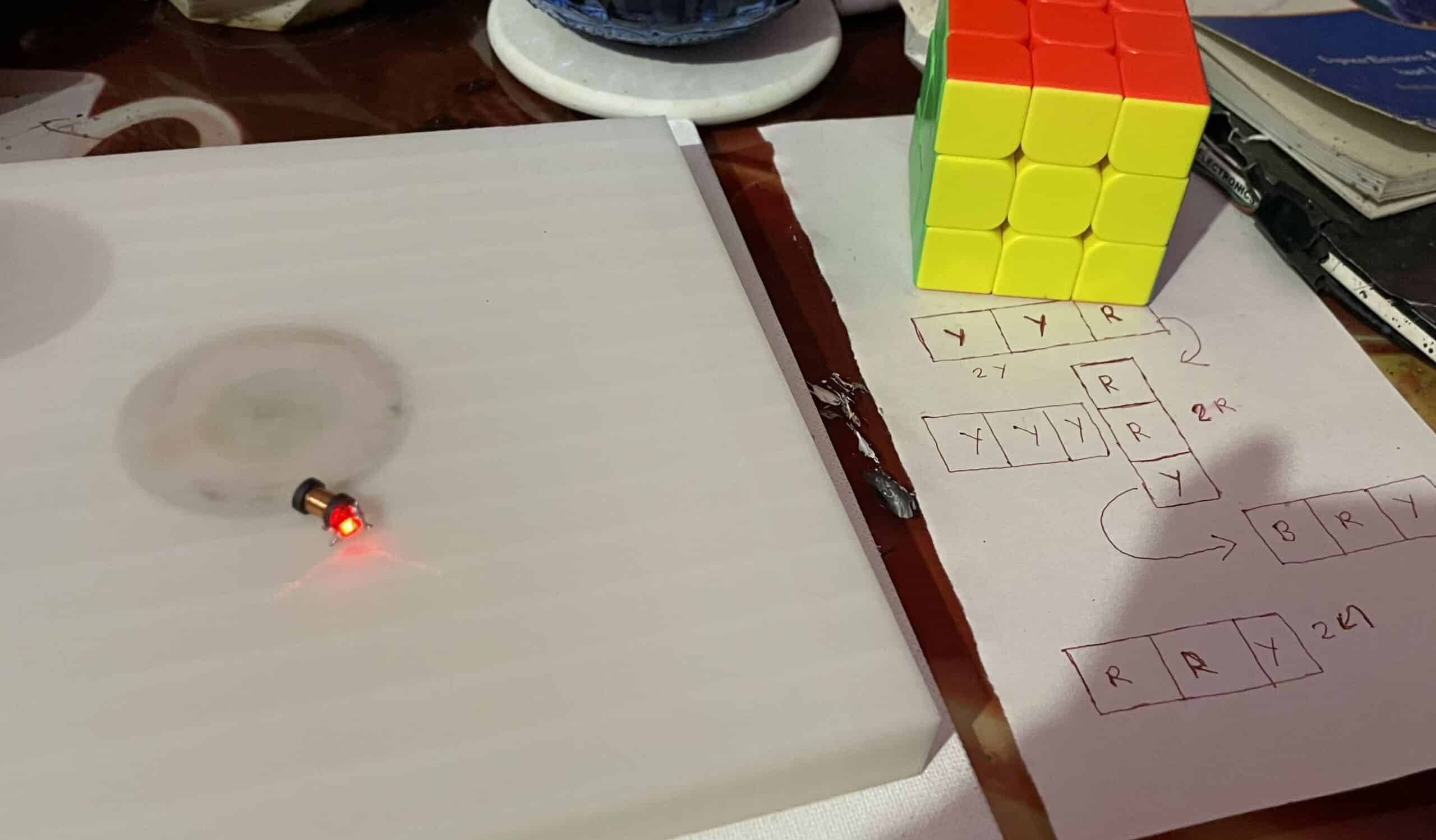
Testing
To test the circuit, connect the LED( from any smart wearable device) to one end of the circuit and bring it near the wireless charger. The device is powered on. Next, the battery is connected to the output of the circuit and brought near the wireless charger in order for charging to begin.