


For Audio processing , Voice recognition and and audio transmission the I2S is needed.
voice recognition, and efficient audio transmission. By utilizing the I2S interface, which supports high-quality digital audio data transfer, this project aims to capture audio input signals from external sources, process them within the indusbaord, which can be used to perform specific audio processing algorithms. Additionally, the I2S functionality will be employed to facilitate the transmission of processed or recognized audio data to other devices or systems, enabling seamless communication and integration within larger audio-centric applications or networks.
Here we try to attach the i2S based MEMS mic array and thnen try to get the I2S buffer data and display it on port in real time and the. The components need is listed in table below.
Bill of Materials
| Components | Description | Quantity | Price |
| IndusBaord | Dev Boord | 1 | 1400 |
| USB Type C | Adapter | 1 | 100 |
| MEMS MIC | I2S MEMS MIC | 1 | 150 |
Coding
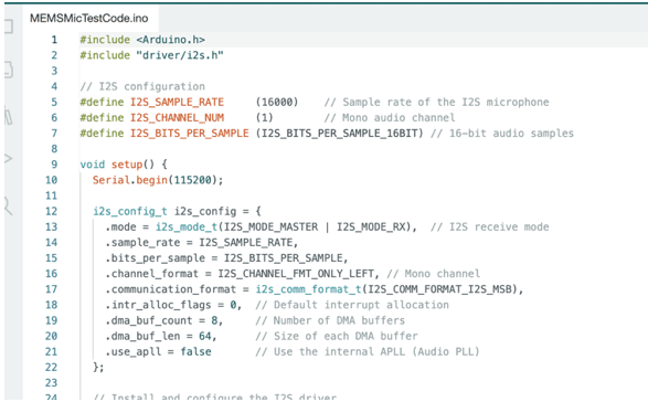
Here Arduino IDE. First I2s driver is insilized in code by default this driver is pre installed in the Borads manage library but in case you get compilation then install this library in Arduino IDE.
Now we are ready to code first you need to include the I2S driver library in code then you can configure the input like simple rate bit rate for audio capture and other things in code
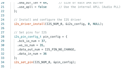
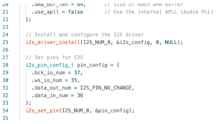
Next you need to set the the pins for the I2S interfacing in code.
It typically consists of three lines:
- Serial Data (SD): This line carries the actual audio data in a serial format.
- Word Clock (WS or LRCLK – Left/Right Clock): This line is responsible for indicating the beginning of each audio sample. It helps synchronize the sender and receiver so that they know when to read the data.
- Bit Clock (BCLK): This line carries the clock signal that determines the rate at which the bits of audio data are transmitted.
Additionally, there might be a fourth line for a Master Clock (MCLK) in some configurations. MCLK provides the master timing reference for the audio data transmission.
Here in code i have used GPIO 36,36,37 for thise I2S pins . Now create the sertup function and then loop function and set the code to capture the audio data and display in serial monitor.
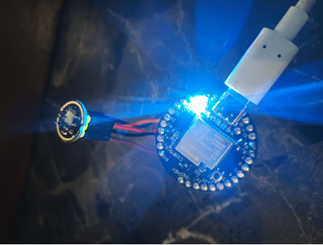
Connection
The MEMS connection pins an be defined and configured in code and you can cnnect accordingly hee in the tested code we have uses 37,35,36 as you can see in the fig beow. Connect all the components as per described in table.
| Indus Board | MEMS |
| 5V | VCC |
| GND | GND |
| 37 | BCK |
| 35 | WS |
| 36 | DATA |
Testing
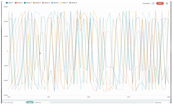
After uploading the code open the serial monitor you can see th I2S data, You can also open the serial plotter to visualise the serial data.
Download Source Code