


Do you want to design a high-efficiency, low-powered e-bike? Then this reference design from Microchip will help you build your own e-bike motor drive. The reference design is suitable for BLDC and PMSM motor drives. The high-efficiency drive is highly customisable and will help you achieve a higher range.
This motor drive reference design from Microchip is a high-efficiency design suitable for e-mobility solutions. The design is suitable for low-powered e-scooter and e-bikes. The reference design can take input from 18V to 24V and deliver a maximum power of 350W. The reference design is capable of driving both a BLDC motor as well as a PMSM motor of up to 350 W power.

The brain of this reference design is a digital signal controller (DSC), dsPIC33CK. The single-core dsPIC33CK Digital Signal Controllers (DSCs) accelerate Digital Signal Processor (DSP) performance for time-critical applications. This design also employs 6 MOSFETs with low RDS(on) which enhances safety as the MOSFETs can handle high phase currents without excessive conduction losses.
The reference design features an XT30 type connector for connecting it to the battery pack. These automotive-grade connectors decrease the chance of short circuits or making a wrong connection with the battery pack.
Both the software and hardware can be used without any additional changes but the firmware of the board can be fine-tuned for specific applications. Tuning the firm can be done using PicKIT4 and MPLAB X IDE In-Circuit Debugger/Programmer which allows fast and easy debugging and programming of the dsPIC.
Block Diagram
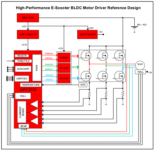
Block diagram of the reference design (source: Microchip)
This reference design is developed to meet the stringent demands of low-powered automobiles such as e-scooters/ebike. This design offers high efficiency, compact dimensions and low cost while providing high performance.
Key Features
• 18V to 42V VBUS Input Voltage Range (cover up to 10S batteries setup)
• Maximum output power: 350W
• 15A RMS (continuous) and up to 27A RMS (for short time) motor phase current
• Low-side shunt resistors on each inverter phase for current measurement (2 mΩ)
• PWM switching frequency range 8 kHz-50 kHz (typical 20 kHz)
• On-board bias generator based on the MCP16331 buck regulator
• Six N-Channel MOSFETs with low RDS(on) (typical 1.9 mΩ)
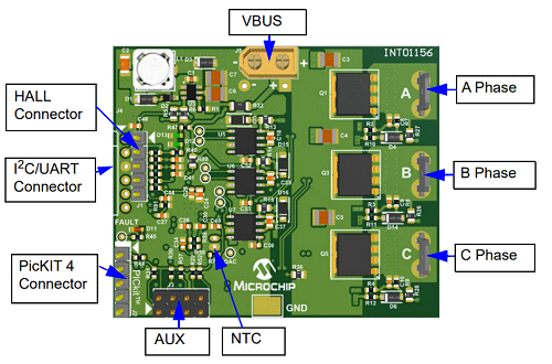
• Faston Tab connectors for motor phases
• XT30 – type connector for convenient connection with the battery packs
• Support for sensored/sensorless motor control algorithms
• PICkit debugger/programmer interface
• Support for on-board temperature measurement (NTC Thermistor)
• Auxiliar connectors for custom functions like I2C, UART, THROTTLE
