


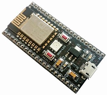
 We need faster tools and media to prove our ideas, and this is where ready-to use modules like Smart Wi-Fi enter. Fig. 1 shows the top side of Smart Wi-Fi module.

The module is low-cost and versatile; all a developer needs is a USB cable and it is ready to work. For software developers, working with hardware is always a pain, and this is one of the biggest reasons why many ideas never exit a computer. Smart Wi-Fi enables making a product quickly and reliably. With open software resources and hardware data, moving to the final product after the proof of concept is also easy.
One of the major aims for writing this article is to show the versatility of this product and show how quick the development can be. In this article a few tests with Smart Wi-Fi are discussed, which show the applicability of this module for development of the Internet of Things (IoT) products.

Circuit and working
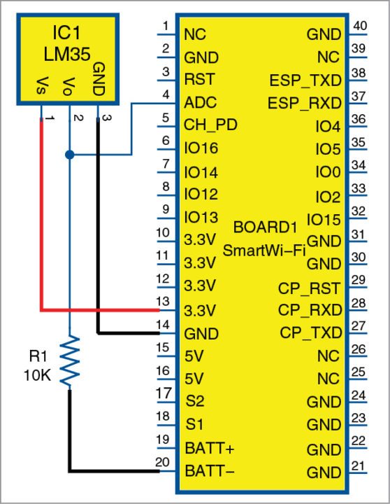
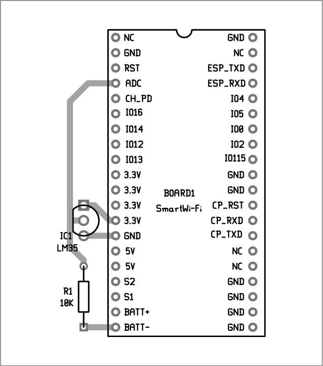
The circuit diagram of the Smart Wi-Fi is shown in Fig. 3. It is built around Smart Wi-Fi module (BOARD1), micro-USB cable, LM35 temperature sensor (IC1) and a resistor (R1).
Smart Wi-Fi has ESP8266 Wi-Fi module along with an onboard voltage regulator, USB port, battery charger, user button and debug RGB LED.
Temperature is sensed by IC1 and its output is measured with ADC pin of BOARD1. BOARD1 sends data to the serial port. Data can be seen in the serial terminal of ESPlorer tool.
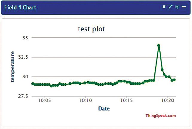
Real-time temperature data is uploaded over ThingSpeak (www.thingspeak.com).
Construction and testing
A single side PCB of Smart Wi-Fi is shown in Fig. 4 and its component layout in Fig. 5.
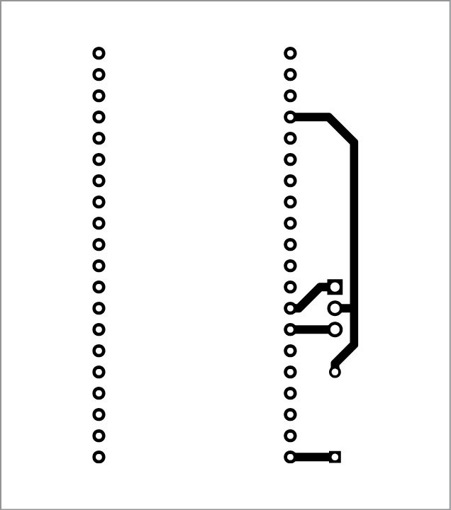
Download PCB and component layout PDFs: click here
ESP8266 module has many tools that are freely available, and you can select these as per your requirement. For a person new to this kind of development, following tools are recommended. Download and install these as per your PC configuration.
1. ESPlorer for serial port interface with Smart Wi-Fi. Click here
2. CP210x USB drivers . Click here
3. Smart Wi-Fi comes with the latest version of NodeMCUfirmware pre-loaded
4. NodeMCU API. Click here
We describe two tests (TEST1, TEST2) in this article. Before downloading the code in Smart Wi-Fi, you will need to connect it to the PC using a micro-USB cable. Start ESPlorer tool and set the port and baud rate [9600 default] and press Open Tab to open the port. It is ready to use now. We have used ESPlorer v0.2.0-rc2 version, and the corresponding test procedure is described below.
Temperature sensor interface with Smart Wi-Fi
The code here is for data read on the ADC and sent to the serial port locally. Open Temperature_Interface.lua file (given in DVD), type =call(“Temperature_Interface.lua”) on the left side of Send and press Send.
We can now observe data into the serial terminal of ESPlorer tool. The code will keep sending data over the serial port every 15 seconds. In the code, we use internal timer # 1 of ESP to call an inline function every 15 seconds. The function reads ADC0 value, which it receives in terms of millivolts, and divides it by ten. As the resolution of LM35 is 10mV per degree Celsius, dividing by ten provides the actual temperature in Celsius. We can print this value to the serial port using print function:
tmr.alarm(1, 15000, 1, function()
current_temp = adc.read(0)/10;
print(fmt(“Temperature : %3.1f C”, current_temp));
end);
Temperature data upload on the Internet using ThingSpeak API
In Test 1, we connected a temperature sensor and observed the data locally. This data can be used in multiple ways as per the application. In Test 2, we will make the same data available on the Internet and it would be accessible from anywhere in the world.
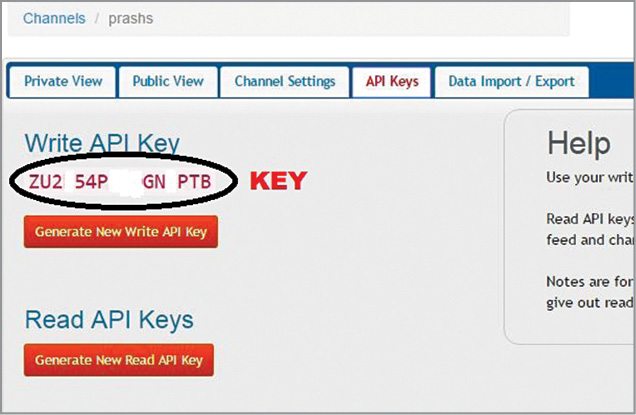
We use ThingSpeak API, which is a freely-available tool used to access and present data over the Internet. Before using ThingSpeak API, you need to create a user account for ThingSpeak and a channel. You will get an API key (Fig. 6) for the channel and then you can upload your data and present it in a graphical form. The only limitation is the frequency of posts, which is limited to 15 seconds.
Before going ahead with data upload, the local Wi-Fi router needs to be paired with Smart Wi-Fi. Use the following command to connect it to your Wi-Fi router:
call(“conenctap”,”your router SSID”,”your router password”);
This command will pair Smart Wi-Fi to the Wi-Fi router you want to connect with. The response will be the IP address assigned to Smart Wi-Fi by the router.
Open ThingSpeak_upload.lua file (given in DVD), type =call(“Thingspeak_upload.lua”) on the left side of Send and press Send. Data output on ThingSpeak API is shown as:
Error: Reference source not found.
The application code that will post data to ThingSpeak server (Fig. 7) is given below.
myKey = “put your API key here”
function post()
call(“setLED”, 2);
field1 = adc.read(0)/10;
print(fmt(“%3.1f”,field1));
call(“httpsend”, “api.thingspeak.com”, 80, “/update?api_key=”..myKey..”&field1=”..field1);
call(“setLED”, 0);
tmr.delay(50);
end
call(“connectap”,” your router SSID “,” your router password “)
tmr.alarm(1, 15000, 1, post)
Applications of Smart Wi-Fi
Smart Wi-Fi is an IoT-enabler tool.The applications it can cater to are only limited by the imagination of makers. The very basic applications could be for smart homes or smart offices.
This module can be used for data logging, data monitoring and more, and provides very good support for product development. It also has all features to act as a full-fledged product.
Using Smart Wi-Fi module, we have seen how easy it is to interface and connect sensors to the Internet. Tools like ESPlorer and open source LUA scripts make development very easy and fast. Platforms such as ThingSpeak add to the benefits and provide support for testing and development of an IoT product.

Really an interesting article. Just a small doubt. In the Block diagram, a line is shown connecting the Thingspeak to Smart Wifi. Does it mean that the Smart Wifi would be able to connect direct to the cloud bypassing the PC? if so, how is it achieved. Thanks in advance.