Opting for an LED bike headlight is quite cost-efficient when it comes to improving your visibility on the road. It makes your presence known to the others and provides you with a clear visibility so that you can avoid dangers and pay attention to the road. Riding a bike with the stock headlight alone is often troublesome!
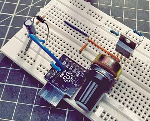
You can now make this inexpensive and easy-to-make LED bike light (primarily to support the stock headlight) that also has a strobe light option. A strobe light, also known as a stroboscopic lamp, makes a biker’s night/foggy-day journey safe because it continuously produces regular flashes of light. It can also be used to warn other vehicles and pedestrians and to clear the path during an emergency. The author’s prototype is shown in Fig. 1.
Circuit and working
Circuit diagram of the LED bike light is shown in Fig. 2. The key hardware in this design is a Digispark ATtiny85 microcontroller development board (Board1), which operates on a 9V USB battery. It is an Attiny85 based microcontroller development board similar to the Arduino line, only cheaper, smaller, and a bit less powerful.

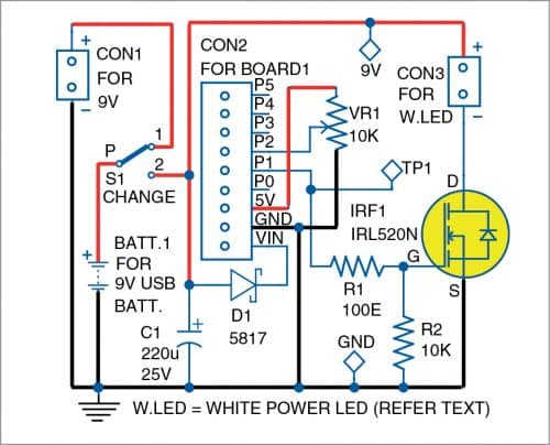
If you are wondering why use a slightly expensive Digispark instead of cheaper discrete components, the reason is the light’s two modes—steady glow and strobe. That means when knob of the 10k pot VR1 is in its minimum position, the LED is on with full brightness, and when it is in its maximum position, the LED is off. Between these two positions, the light source acts as a strobe light fluctuating at a frequency between 25Hz (fast strobe) and 2Hz (slow strobe). The pot is powered by Digispark’s onboard 5V DC regulator, and its wiper (middle terminal) is connected to analogue input A1 (P2) of the Digispark.
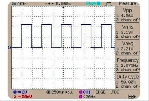
Likewise, Digispark’s P1 I/O pin goes to the gate of the lamp driver MOSFET IRL520N (IRF1). The 100-ohm resistor R1 is the gate resistor of IRF1 whereas the 10k resistor R2 works as a pull-down resistor. These two resistors are essential because the gate of the MOSFET is basically a capacitor. So, when a voltage is applied to the gate without the gate resistor, the resultant inrush current can damage the microcontroller’s I/O if it is unable to quickly source that much current. Here, R1 limits the maximum current and R2 assures that IRF1 is always in a known state. Fig. 3 shows a casual oscilloscope snap captured while poked into TP1.
If you are using a non-USB version of the 9V battery, the 2-pin connector CON1 can be used to connect its external charger to recharge the battery. It is worth noting that the nominal output of most rechargeable 9V LiPo batteries is only 7.4V (8.2V maximum). So, there is a possibility that the Digispark board will reset due to power drop when a high-power lamp is energised. The 220µF electrolytic capacitor C1 mitigates that episodic hiccup. Since Digispark has an onboard voltage regulator, you can safely use a 2S, 3S, or 4S LiPo battery pack instead of the proposed 9V USB battery.
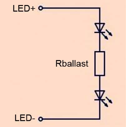
There is no fixed rule on how many lumens of brightness you need for your bike light, but typically you will need approximately 500-lumen front light to see where you are going than to be just seen. So, use a pair of one-watt ‘star white’ LEDs in series as the light source, and try to tweak it later after some road trials. Include a suitable ballast resistor to limit the operating current, as shown in Fig. 4.
The LED lamp needs some optics to improve the light coming from it. Nowadays, LED reflector/lens plus a holder come together as a kit. However, while choosing it, check its ‘beam angle’ specs—the angle over which the light would be distributed. Narrow beam angles (for example 40°) have a tight beam of light and wide beam angles (around 120°) have a larger coverage for wide area lighting.
Also note that a clear lens provides a crisp-edged beam of light and a diffused lens offers a more uniform light output, especially when multiple lamps are used.
Warning. Sometimes strobe lighting can trigger seizures in persons suffering from photosensitive epilepsy (https://psychology.wikia.org/wiki/Photosensitive_epilepsy)!
Construction
If you are considering building a real-world model of this LED bike light, please use a rigid, waterproof enclosure. Some reference models are shown in Fig. 5.
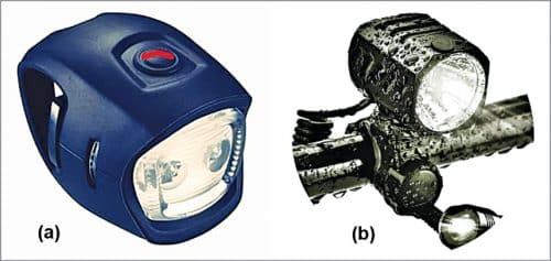
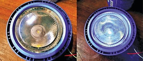
For a quick functionality test, a large white LED torch head can be scavenged from an old torchlight to act as the light source, as shown in Fig. 6.
Download Source Code
Software
The Arduino’s pretty simple sketch (code) ported for Digispark is given here. It turns the lamp drive pin (P1) on and off with delays in between set by the pot connected to analogue input A1 (P2). In order to get much better strobes, however, a bit of complex math is applied in an interesting way to fine-tune the time delay function.
/* LED Bike Light v1
* Key Hardware: Digispark Attiny85
Development Board
* Arduino IDE: 1.8.13 (Windows10x64)
* Author: T.K.Hareendran
* Adapted Open-Source Code. Thanks to
www.bukovac.si */
int headLamp = 1;
int val = 0;
int onTime = 0;
int offTime = 0;
void setup() {
pinMode(headLamp, OUTPUT);
}
void loop() {
val = analogRead(1);
onTime = val;
offTime = (-2000000 / (onTime + 1000)) +
2000;
onTime = onTime / 4;
offTime = offTime / 4;
if (onTime > 12) {
digitalWrite(headLamp, HIGH); }
delay(onTime);
if (onTime < 250){
digitalWrite(headLamp, LOW); }
delay(offTime);
T.K. Hareendran is an electronics designer, hardware beta tester, author, and product reviewer