


 Here is a circuit meant for babies for generating various light patterns on eight LEDs. Lights pattern generator circuits available in the market are fitted with toys, and are used by babies for play and entertainment. These toys are bulky, analogue in nature and costly.
The biggest drawback is that these generate very few patterns. This circuit is low cost. It can be used as a lightning effects display system in a room.
Circuit and working
The circuit diagram of the pattern generator is shown in Fig. 1. It is built around AT89S51 microcontroller (IC1), eight LEDs (LED1 through LED8), 11.0592MHz crystal (XTAL1) and a few other components.

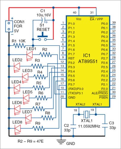
The microcontroller (MCU) has various features incorporated in it. It has 40 pins and four inbuilt ports (P0, P1, P2, P3). Each port has eight pins, and all behave like 8-bit registers. Each pin has an input/output line, which can be used for input as well as output, that is, read data from device like sensor or provide output to an output device like LED or LCD. Some ports have dual functionalities like interrupt, counters, timers, etc.
Atmel-based AT89S51 has two types of memory: RAM that has 256 bytes of memory and electronically erasable and programmable read-only memory (EEPROM) that has 8k bytes of memory. RAM is used to store data during execution of a program. EEPROM is used to store the program itself. EEPROM is the flash memory, which has been used to burn the program.
A crystal oscillator of 11.0592MHz frequency is connected to pins 19 and 18 of IC1, that is, XTAL1 and XTAL2. It is applied to generate clock pulses. Clock pulses are used to provide the means for timing calculation, which is required to tune all operations.
The most commonly used crystal is quartz, which is a resonant oscillator circuit. 33pF capacitors are used to oscillate the crystal. Pin 31 (EA/VPP) is connected to VCC (5V), which is an active low pin. This should be connected to VCC, when external memory is not in use.
Pins 30 (ALE/PROG) and 29 (PSEN) are used to connect the MCU to the external memory. Pin 31 tells the MCU to use external memory, when connected to ground. Since we have not used any external memory, we connected pin 31 to Vcc.
Pin 9 is used to reset the MCU, or to start the program again from the beginning. It resets the MCU when connected to 5V. We have used standard reset circuitry, 10-kilo-ohm resistor and 10µF capacitor to connect the reset pin.
Software
The software is written in C language. Compile the code using Keil software. Logic behind the software is described briefly for easy understanding and editing. (Topview programmer was used for programming the IC in EFY Lab.)
Download Source Code
Construction and testing
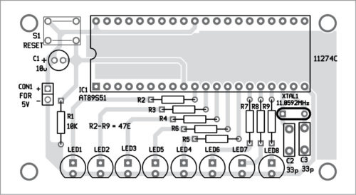
An actual-size PCB layout for the pattern generator is shown in Fig. 2 and its components layout in Fig. 3. After assembling the circuit on the PCB, connect the 5V supply across CON1. Connect reset switch S1 and all LEDs on the front panel.
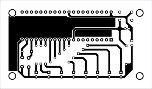
Download PCB and Component Layout PDFs: click here
The circuit can be tested on the assembled PCB or breadboard. Give 5V supply voltage to the MCU.
This circuit was tested on babies in the age group ranging from two months to two years. They found the LED light patterns quite interesting and fascinating.
Modification of light patterns can be done in the software to generate various design patterns.
Navpreet Singh Tung is assistant professor in department of electrical engineering, Bhutta Group of Colleges, Punjab
