


This Light Intensity Controller Project describes how a simple circuit can be designed to control the intensity of a string of LEDs. The circuit is based on a common 555 timer IC that employs pulse width modulation (PWM) technique to control the voltage. The 555 IC is driven in an astable mode. The same circuit can be used to control the speed of a DC motor as well.
The most important component in this Light Intensity Controller project is the 555 timer IC along with the MOSFET that works as a switch. The circuit works like a power electronics buck converter, which can be used to step down the DC voltage.
Components required for the project are listed in the table below.
| Bill Of Material | |
| • 555 Timer IC • IRFZ44N • 1k Resistor • 200-ohm Resistor |
• 100nF Capacitor • 1nF Capacitor • 3×IN4001 Diode • 100k Potentiometer |
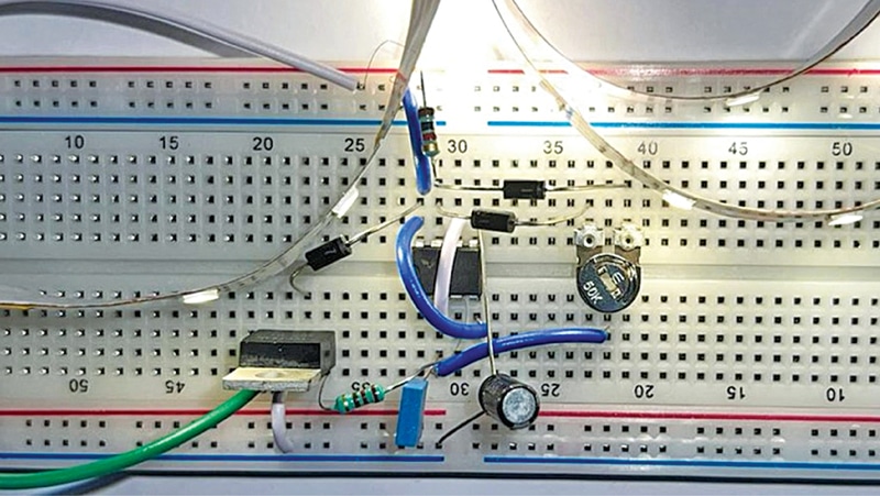
Designing a PWM LED controller using 555 timer is absolutely straightforward and requires only a few components. From the diagram shown in Fig. 1 it is clear that the whole circuit is built around the 555 IC as the PWM generator. Hence, we can control the switching frequency and therefore the brightness of the LEDs with the help of passive and active components connected to it.

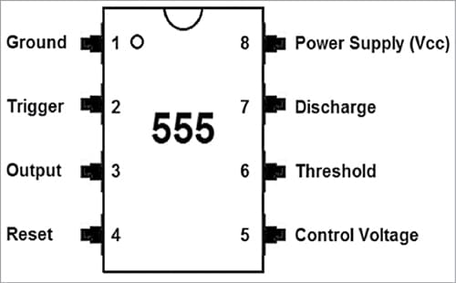
The 555 timer is a commonly used 8-pin integrated circuit (IC) that is used for a variety of applications, including pulse generator, oscillator, and timer. The operating voltage of the IC may vary from 4.5V to 16V. Fig. 2 shows different pins of the 555 IC.
PWM control using 555 IC
Before delving further into the circuit, let us understand the technique of PWM, which is also known as pulse duration modulation. It is a method of controlling the average power delivery by pulsating the DC current. In this circuit, the average power is controlled (reduced) by effectively chopping it up into discrete parts by connecting and disconnecting the power source in fast succession.
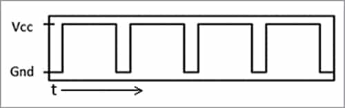
To achieve a PWM signal, the 555 timer is driven in an astable multivibrator mode. As the name suggests, the 555 timer has no stable state in this mode, but rather two quasi-stable states that change from high to low and low to high. In simpler words, in this mode the 555 timer turns on and off at a very high speed, which can be considered as 0 and 1 in the binary context, thus producing a square wave signal, as shown in Fig. 3.
Connecting the 555 IC
- Pin 1 is the ground pin and is connected to the -ve rail.
- Pin 8 is the VCC pin and is connected to the +ve rail.
- Pin 2 and pin 6 are the trigger pin and threshold pin, respectively, which are connected with the ground through a 1nF capacitor timing capacitor.
- Pin 3 is the output pin, which emits the PWM signal and is connected to the gate of the MOSFET.
- Pin 4 is the reset pin, which can be used to reset the operation. But we are not using it, so connecting it permanently to the +ve rail.
- Pin 5 is the control voltage pin, which is connected to the ground with a 100nF capacitor. It keeps the output stable and provides immunity against electrical noises.
- Pin 7 is the discharge pin, which is connected to the +ve input with a 1k resistor and is also connected to the inverted diode setup and helps change the duty cycle.
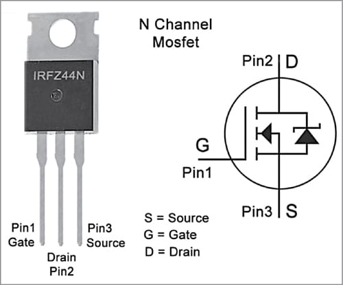
Fig. 4: Pin configuration of IRFZ44N
IRFZ44N for high-speed switching
The 555 timer IC is capable of outputting a small amount of current as an output, which can be directly used only for a handful of LEDs. But in order to drive a long LED string, or control the speed of a motor, the current is not enough. To overcome this problem a MOSFET is used in the circuit whose gate is connected to the output of IC 555. The N-channel MOSFET used provides a negative switching control to the circuit.
For our circuit we are using N-channel MOSFET IRFZ44N as a switch, which can be excited by the output of 555 timer and is suitable for the voltage requirement of our load. It has following specifications:
VDSS=55V
RDS(on)=17.5mΩ
ID=49A
Controlling intensity of LED
As mentioned earlier, passive components in the resistor and capacitor (RC) network can be used to control the duty cycle and therefore the brightness of the LED.
Duty cycle (D)=PW/T
Here, D=Duty cycle, PW=Pulse Width (pulse active time), and T= Total period of the signal
Duty cycle represents the ratio of time when the load is connected to the power compared to the time load is not connected to the power. The higher duty cycle means that the load is connected to the power source for a longer duration compared to a lower duty cycle.
This technique can be used to control the intensity of LEDs or the speed of a motor, When the duty cycle is high, the LED glows brighter or the speed of the motor will be greater. To reduce the intensity of the LEDs, or to reduce the RPM of the motor, the duty cycle needs to be reduced.
Intensity of LEDs=(On time/ total time)×max illumination
Speed=(On time/total time)× max speed
Testing
To check whether the circuit works properly or not, you may use a 12V battery pack (like the author) as input. Since we are using an N-channel MOSFET and providing a negative switching control, the positive terminal of the load is always connected while the negative terminal is connected to the drain of the MOSFET, which is driven by the 555 timer IC. Fig. 5 shows the LED strip glowing at the maximum brightness.

To reduce the LEDs’ intensity, turn the knob of the potentiometer anticlockwise, which reduces the brightness of LEDs, as shown in Fig. 6.

The same setup may be tested with a 12V DC motor. We should be able to control the speed of the motor.
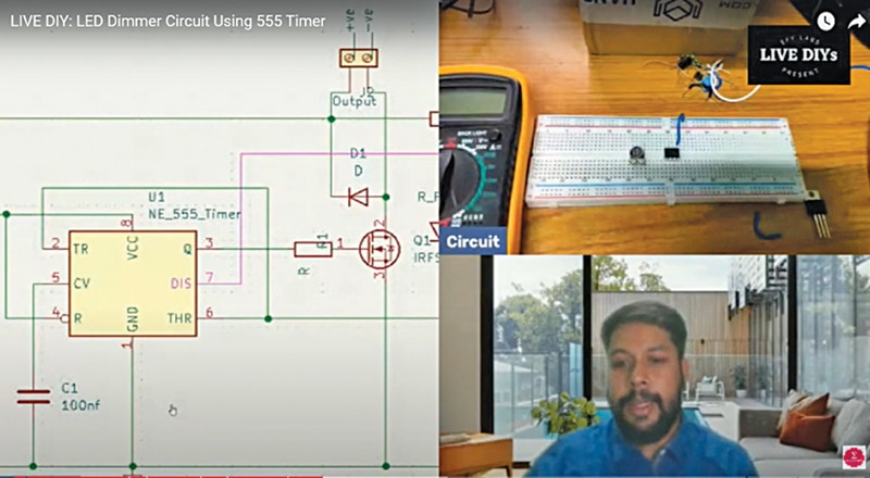
BONUS. You can also watch the VIDEO of the tutorial for this DIY project.
The author, Sharad Bhowmick, works as a Technology Journalist at EFY. He is passionate about power electronics and energy storage technologies. He wants to help achieve the goal of a carbon neutral world.
