


 MagSafe, a magnetic technology embedded into the internal engineering of iPhone 12 model, was originally created as a safety feature for MacBook charging cords. It creates a new ecosystem of accessories for easy attachment and faster wireless charging. The cost of a wireless power bank with MagSafe ranges from ₹5000 to ₹7000. Apart from being expensive, it is difficult to procure from the market.
| Bill Of Material | ||
| Component name | Quantity | Description |
| Inductor coil | 1 | For wireless power |
| 5V stepup charging BMS | 3 | 5V stepup charging module |
| Wireless power TX module | 1 | Power transmitter |
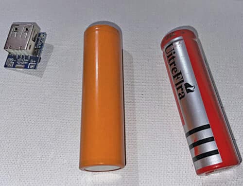
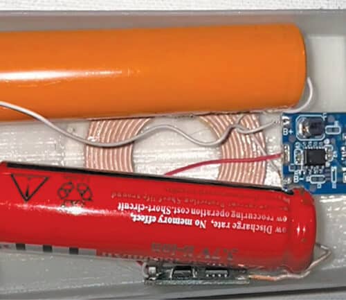
| 3.3V rechargeable battery | 2 | 2000mAh or 1000mAh |
| 3D printed case | 1 | Powerbank case |
This DIY project is of a wireless power bank with MagSafe, which can not only charge iPhones but also other compatible devices (including IoT devices). It offers the benefit of having a wireless powering system, MagSafe technology, and a USB charging system that is compatible with many devices.

Designing
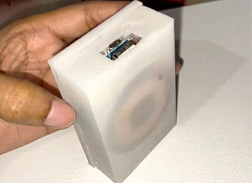
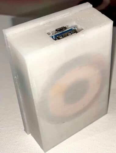
The size of the battery is important for designing a proper case. Both the battery and the charging module have to fit inside the case, which has to be cut to make provision for input power charging (USB) and output power. A cavity is also made on one wall of the case for the coil and MagSafe magnet to be placed, as shown in Fig. 3.

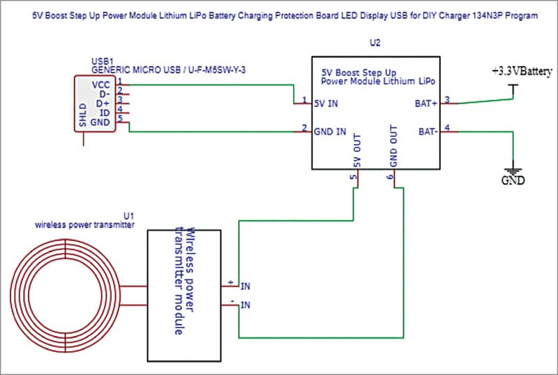
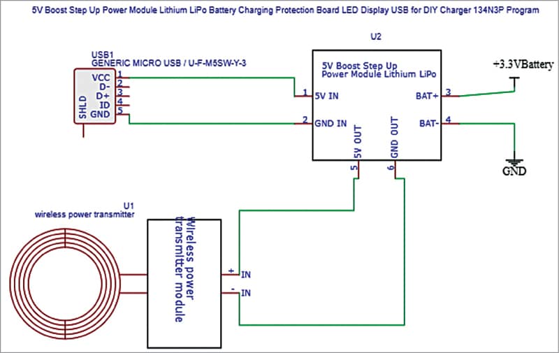
For the circuit, we can either use a 5V step-up battery management IC or a module. A TP4056 one-ampere battery charging module was used in the author’s prototype. The module’s output is connected to a wireless transmitter, as shown in Fig. 5.
Connections
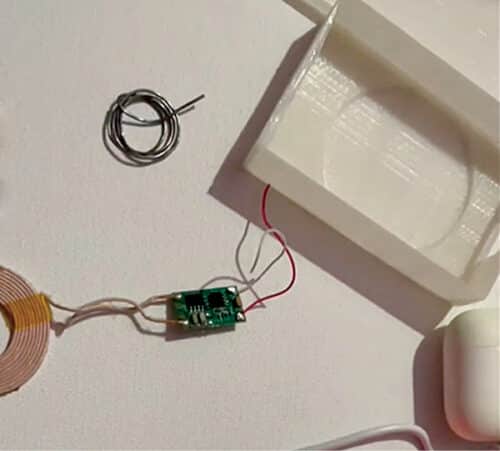
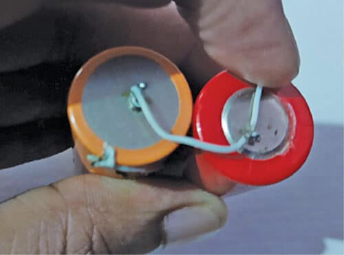
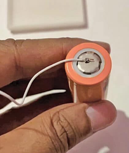
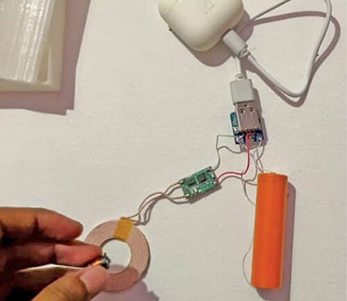
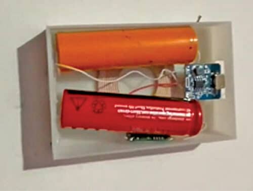
The battery terminals are soldered either with the wires directly or a battery pack connector strip. In case of multiple batteries being used, make sure to connect the batteries in parallel (see Fig. 6). Next, connect the battery step-up charging module as shown in the circuit diagram. The wireless charging coil should now be soldered with the input of the wireless power transmitter module and its output with the charging module output pins (see Fig. 7 through Fig. 10).
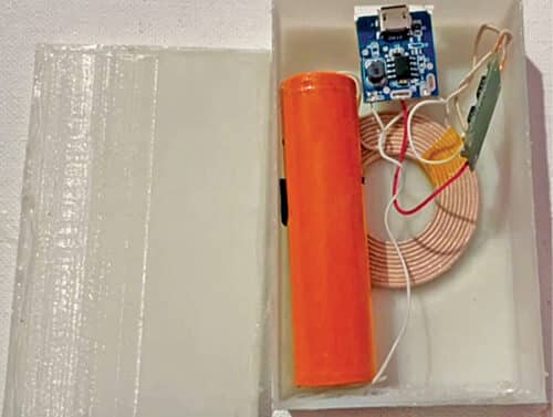
The coil may now be fixed in the cavity with a magnet for MagSafe. Above this fix the battery along with the BMS module in USB cavity of the 3D-printed case. Finally, fix the top cover (see Fig. 11 through Fig. 14). For MagSafe, fix the circular magnet in cavity with glue.

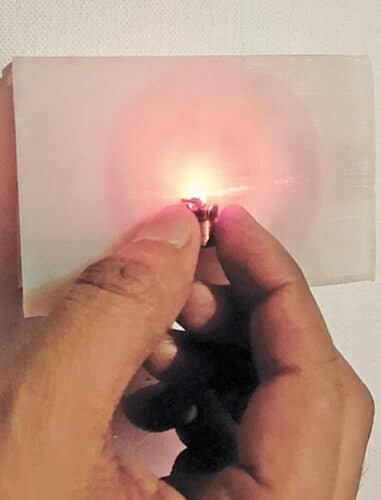
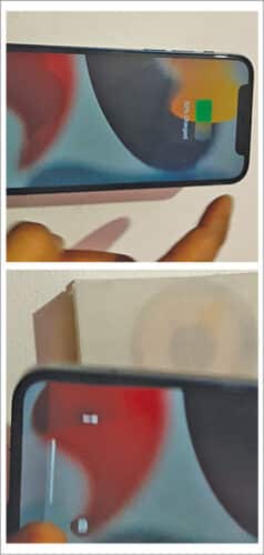
Testing
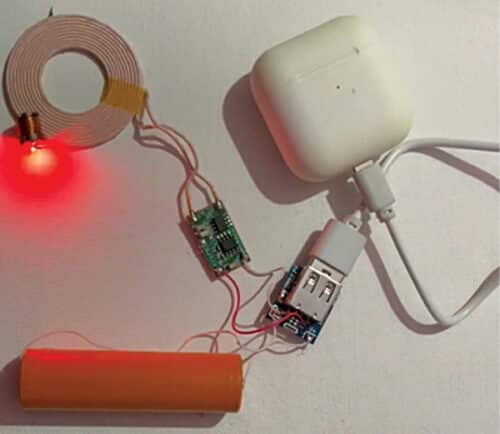
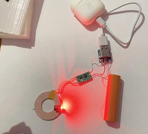
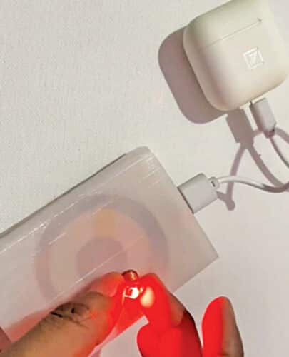
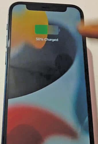
To test the circuit, plug in any device to the USB and notice it charging. (In the pictures an Airpod case is shown plugged in.) Next, bring any wireless device (a wireless LED is shown in the pictures) and see the LED glowing, as shown in Fig. 19, as the power bank emits power in the form of electromagnetic waves. A phone can be charged by placing it on the device, as shown in Fig. 20.
Ashwini Kumar Sinha is a technology enthusiast at EFY