


In the era of advancing technology, the need for security has become an essential part of everyday life. One of the basic and most widely used security measures is a lock. With the advent of smart technologies, the concept of smart locks has emerged, which are more secure and convenient than traditional locks. Smart locks use digital codes instead of physical keys, making them less prone to security breaches.
This project aims to design a smart lock system that can detect a preloaded sequence of digital inputs and unlock the lock only when the correct sequence is entered. The project utilizes a mixed signal design, combining both analog and digital circuits. The analog circuit includes a clock generator and the lock, while the digital circuit includes a Finite State Machine designed using Verilog.
Implementation
A. Moore machine
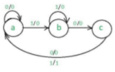
A Finite State Machine (FSM) is said to be Moore state machine, if outputs depend only on present states. 101 non-overlapping sequence detection using Moore state machine involves the following steps. Let S0, S1, S2, S3 are the three states taken for sequence detection where 00,01,10,11 corresponds to S0, S1, S2, S3 states.

- Step 1 − S0 is the start state on input ‘0’ goes to S0 and on ‘1’ goes to S1 generating output 0.
- Step 2 − S1 on ‘0’ goes to S2 and on ‘1’ goes to S1 generating output 0.
- Step 3 − S2 on ‘0’ goes to S0 and on ‘1’ goes to S3 generating output 0.
- Step 4 − S3 on input ‘0’ goes to S0 and on ‘1’ goes to S1 generating output 1 as desired sequence is detected.
- Step 5 – The above steps are repeated to find the sequence
Input: 0110101011001
Output: 0000100010000
B. Design Flow
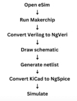
The main aim is to create is to the model of the Smart lock system and to use it in a Mixed signal processing circuit to complete the process. It involves following steps.
- In eSim toolbar, Makerchip is selected and top level Verilog module is selected and Verilog code is uploaded
- Edit in MakerChip IDE i.e. inbuilt in eSim
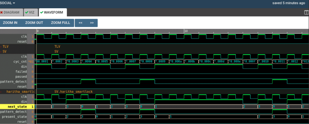
- Remove the errors and observe the waveforms for randomized inputs
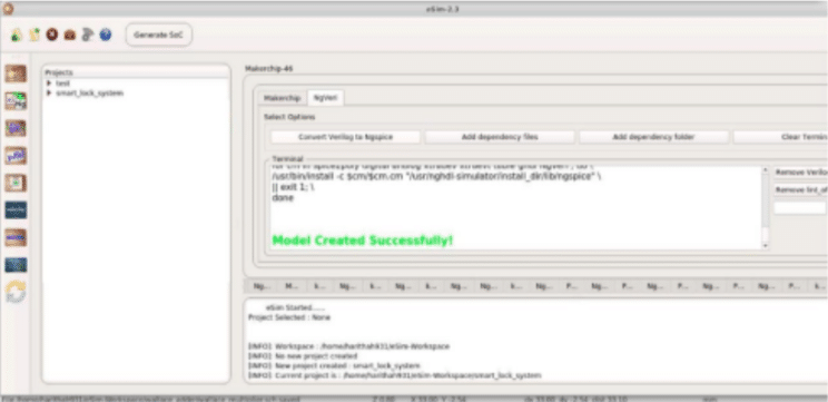
- Open NgVeri and convert Verilog to NgSpice , thus it creates a Verilog model successfully
- Create new project and draw schematic using Verilog model created, ADC and DAC.
- Generate the netlist in the schematic window
- Convert Kicad to NgSpice
- Simulate the waveform
C. Verilog Code
The verilog code is written over a text editor by using behavioral flow modelling. The code contains main module named haritha_smartlock with output pattern_detect and input clk, reset, din. S0, S1, S2, S3 are the three states taken for sequence detection. 00,01,10,11 corresponds to S0, S1, S2, S3 states. S0 is the start state on input ‘0’ goes to S0 and on ‘1’ goes to S1 generating output 0. S1 on ‘0’ goes to S2 and on ‘1’ goes to S1 generating output 0. S2 on ‘0’ goes to S0 and on ‘1’ goes to S3 generating output 0. S3 on input ‘0’ goes to S0 and on ‘1’ goes to S1 generating output 1 as desired sequence is detected.
module haritha_smartlock (input clk , input reset, input din , output reg pattern_detect); reg [1:0] present_state , next_state;
always @ (posedge clk, posedge reset)
begin
if(reset)
present_state <= 2’b00;
else
present_state <= next_state;
end
always @ (*)
begin
case(present_state)
2’b00 : begin
if(din)
next_state = 2’b01;
pattern_detect = 1’b0;
end
2’b01 : begin
if(!din)
next_state = 2’b10;
pattern_detect = 1’b0;
end
2’b10 : begin
if(din) begin
next_state = 2’b11;
pattern_detect = 1’b0;
end
else begin
next_state = 2’b00;
pattern_detect = 1’b0;
end
end
2’b11 : begin
next_state = 2’b00;
pattern_detect = 1’b1;
end
default : begin
next_state = present_state;
pattern_detect = 1’b0;
end
endcase
end
endmodule
D. Makerchip Block
Using NGVeri and the above Verilog Code the smart lock Model was created.
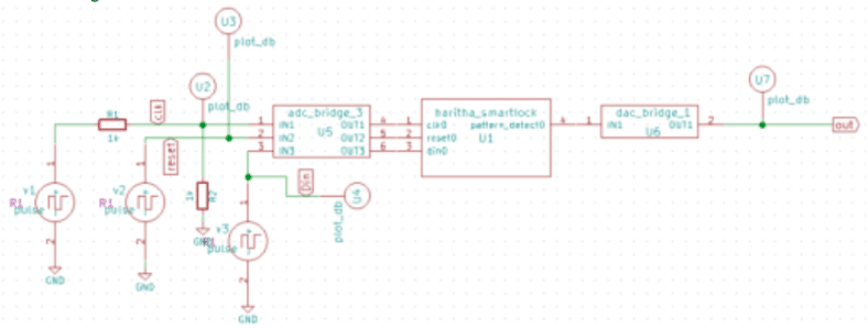
E. Schematic Model
The model of the smart lock is accessed as a component in the tool panel of the schema editor. The Analog to Digital converter is added at the input ports of the model and the Digital to analog converter is added at the output end of the model. The pulse voltage sources are attached to the input lines and the low pass filters are attached to each output line.The Mixed Signal Circuit is made up of Two Parts Digital and Analog. In this case the smart lock Model is the Digital Part and the ADC DAC Bridge is the Analog Part in the Schematic. Create new project and draw schematic using Verilog model created, ADC and DAC. After Drawing the Schematic the netlist is generated and then the KICAD to NGSPICE Converter is used.
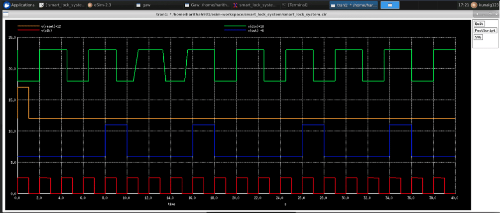
Result
ADC is used at the input end to provide the analog input which will be converted into digital data and is fed to Verilog model created. Only when the user gives correct input to our smart lock system (which matches with the preloaded sequence in the FSM) the lock will open otherwise it will remain closed. At the positive edge of clock and positive reset the sequence detecting starts.
Conclusion
When the user gives correct input to our smart lock system (which matches with the preloaded sequence in the FSM) the lock will open otherwise it will remain closed . At the positive edge of clock and positive reset the sequence detecting starts. The design comprises of both analog as well as digital circuits. Here clock generator and Lock acts as analog circuits which are generated using eSim (a free and open source EDA tool for circuit design, simulation, analysis and PCB design) and the FSM is the digital circuit.It acts as sequence detector and is written in Verilog. Thus a secured smart lock system is designed using mixed signal. This mixed signal circuit can be used in any device irrespective of the kind of (digital or analog ) fed to the Integrated Circuit.
Overall, the software tools used in this project provided a complete design flow for the smart lock system. The tools enabled the user to design, simulate, analyze, and create the layout for the circuit. The open-source nature of the tools made them accessible and affordable for everyone, and the user-friendly interface made it easy to use them even for beginners.
