


 Here is a simple 5-watt mono audio amplifier using IC TA7222 that drives a 4-ohm speaker using a 9V battery or a 9V DC adaptor. You can also make a stereo amplifier by using two identical circuits.
Circuit and working of Mono Audio Amplifier
Circuit diagram of the 5-watt mono audio amplifier is shown in Fig. 1. Apart from audio amplifier TA7222 (IC1) and a 4-ohm speaker (LS1), this 5-watt AF amplifier uses a few resistors and capacitors, a potmeter and two connectors.
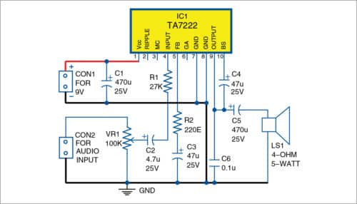
IC TA7222 (IC1) is the heart of the circuit. This IC has ten pins. Pin 1 is connected to +9V power supply. 470µF, 25V capacitor (C1) connected between +9V and ground acts as a filter. Pins 2 and 3 of the IC are not used. Pin 4 is connected to audio input terminal through potmeter VR1, capacitor C2 and resistor R1. Potmeter VR1 is used to control the audio input signal.
Pin 5 of the IC is connected to the ground through resistor R2 and capacitor C3. Pin 6 is not used. Pins 7 and 8 are grounded. Capacitor C4 is connected between pins 9 and 10. Pin 9 is connected to the ground through capacitor C6. It is also connected to the 4-ohm speaker (LS1) through capacitor C5.
Construction and testing
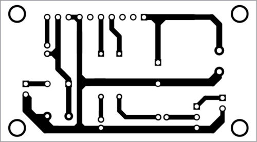
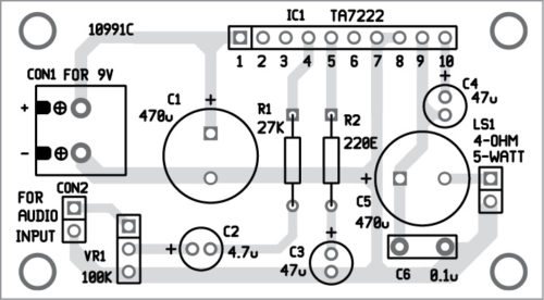
An actual-size PCB layout of 5-watt audio amplifier using IC TA7222 is shown in Fig. 2. Its components layout is shown in Fig. 3. Audio input is given at CON2.
Download PCB and component layout PDFs: click here
After assembling the circuit, do calibration and adjustment as follows: Connect 9V battery to the circuit at CON1. Connect 4-ohm, 5-watt speaker at LS1. Now gently adjust the volume-control potmeter (VR1) to mid position. Take a metal screw-driver and gently touch at the audio input (CON2). You should hear humming sound from the speaker. If so, your amplifier is ready to use.
After calibration, enclose the assembled PCB in a small plastic box.
Note
1. This circuit can work with power supplies ranging from 6V to 12V DC.
2. Do not use a high-wattage soldering iron for IC1 as it can damage the IC. Use a suitable heat-sink to protect IC1 from overheating.
Datasheets says
operating supplay voltage is 18V
P out =5.8W at vcc = 13.2v Rl=4 ohm
P out= 9.3W at vcc= 13.2v Rl=2 ohm
thank you
Very easy to construct simple amplifier with very few external components.