


 This circuit produces an alarm whenever someone comes near the spotting range of its passive infrared (PIR) motion sensor. It can be used as a security system to guard your home and other property, if utilised properly. The author’s prototype is shown in Fig. 1.

Circuit and Working
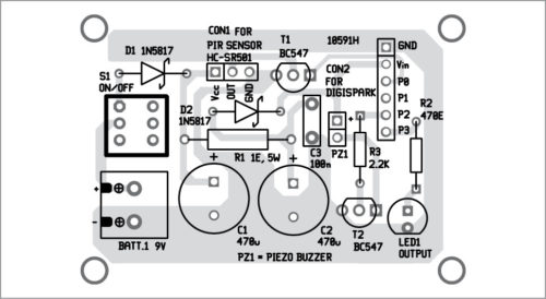
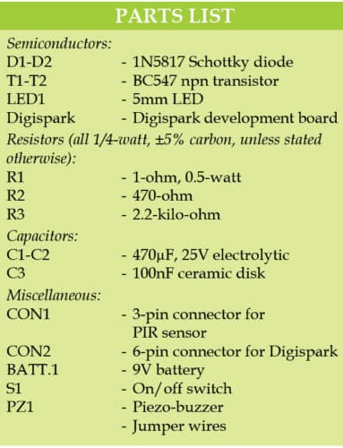
Circuit diagram of the motion detector security alarm is shown in Fig. 2. It is built around a Digispark board, PIR sensor, 9V battery (BATT.1), resistors (R1 through R3), capacitors (C1 through C3) and a few other components.

Despite its small size, Digispark board is packed with many capabilities. Apart from having fewer I/O pins, it can do most of what the microcontroller (MCU) in Arduino board can do. It can also be programmed using Arduino IDE software.

Building the circuit is easy. You need two essential components: a PIR motion sensor module (HC-SR501) and a Digispark (Attiny85) USB development board. As both these are made to operate on batteries, you can use a standard 9V 6F22 battery, or any other 9V rechargeable battery, as the power source. Switch S1 is the master power on/off switch.
Both the PIR sensor and Digispark have in-built voltage regulators and, hence, input DC supply (9V) is pre-regulated by their internal circuitry to develop required working voltages.
Output (OUT) from the PIR sensor is connected to input pin P0 of Digispark through a BC547 level inverter (T1). No pull-up resistor is required here because internal pull-up of Attiny85 is enabled. Output pin P3 of Digispark drives the LED (LED1), while pin P2 controls the switching of the piezo-buzzer (PZ1) through another transistor (T2).
Digispark board
For details on Digispark, refer Getting Started example in the documentation available at http://digistump.com/wiki/start. However, make a note of some significant details given below.
1. Digispark requires Arduino IDE 1.6.5 or later version.
2. Before plugging Digispark board into the USB port of your PC, or before running Arduino, download and install the requisite DigiSpark driver from here.
3. Do not plug in Digispark into the USB port before invoking the upload instructions from Arduino IDE. To do that, hit Upload. The status box at the bottom will ask you to plug in Digispark. At this point, plug it in. If there is any problem, unplug it and plug it back in.
4. If you unplug Digispark and plug it back in, or attach it to another power source, there will be a delay of five seconds before your program (digi_motion.ino) will run.
5. After successfully uploading the program to Digispark, plug it out from the USB port.
Construction and testing
An actual-size PCB for the motion detector security alarm is shown in Fig. 3 and its components layout in Fig. 4.
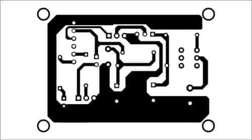
Download PCB and component layout PDFs: click here
Construction can begin by first mounting the discrete components on the PCB or perfboard, followed by the motion sensor and Digispark module. Note that, connector CON1 is for the PIR sensor, and CON2 is for Digispark.
You can experiment with onboard potentiometers in the motion sensor module (HC-SR501) to adjust the timing period (delay) and detection threshold (sensitivity). You can also change the delay in the program (digi_motion.ino).
After construction, enclose the circuit in a suitable box and fit the power switch on the back of the enclosure, as shown in the prototype (Fig. 1). Connect a 9V battery for power supply to the circuit.
After selecting a location for the installation of the circuit, turn on the switch (S1) and wait for 60 seconds for the PIR sensor to initialise. LED1 will flash intermittently to indicate the system status. When the circuit detects motion, the piezo-buzzer (PZ1) will make a sound and LED1 will start blinking rapidly.
Keep the circuit away from heat sources such as radiators, heating ducts and stoves. Also, do not expose the PIR sensor to sunlight or rain. If the alarm sounds at random, it could be because the device is located too close to a heat source. In that case, change the location or direction of the sensor unit.
T.K. Hareendran is founder and promoter of TechNode Protolabz
Motion Detector with DigiSpark is very interesting project, but program digi_motion.ino is missing.
Could you be so kind to send me, please.
Regards, Denis Papp
Thanks for the feedback!
You can download the code from here: http://efy.efymag.com/admin/issuepdf/Motion%20detector%20for%20security%20alarm.rar