


 Today we will design a simple optical flow-based motion detection system that tracks the motion and gives us displacement data based on optical flow. It helps us in making cameras that shoot video based on the movement of any animal or object or alerts if there is any slight movement in objects using optics flow.
Many times we need motion detection and also want to track the displacement of object and their movement. Human motion detection is easy to do as microwave radar and PIR motion sensors are there that track human motion and alert but for non-living or simple objects, motion tracking is a bit difficult and these are often used and needed in robotics or in drones.
Like in drones, we use object motion detection to move the drone or make the drone follow the motion of any moving vehicle or any object or to hover the drone on a particular object. It is also useful in an optical flow-based positioning system. In the camera, we can use it to stabilize the camera lens according to face or object movement using optical flow.

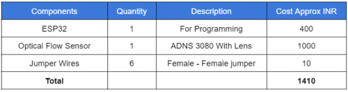
Bill of Materials
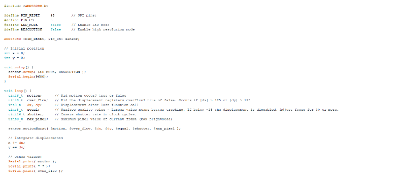
Optical Flow Motion Detection – Coding
First, we need to install the ESP32 board to Arduino IDE and then open the library manager and search ADNS3080 library and install that.
After installation, include the ADNS code, then define the NS pin number for the sensor.
Here I have used pin 5 for that, then we create the setup function where we will start the serial port with a baud rate of 9600 or any other baud rate of your choice and then we will create the loop function where we will check the optical flow sensor data and process the frames from the optical flow sensor and try to get the motion data if there is motion.
Then we will also try to get the displacement in the 2D x and y-axis.
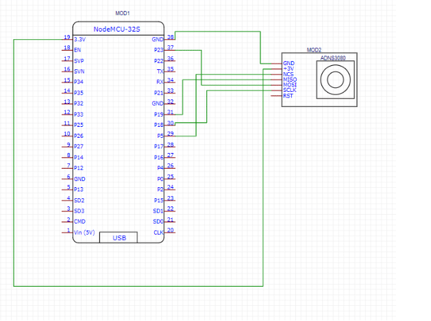
Motion Detection System – Circuit Diagram
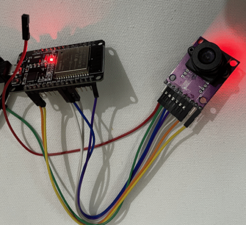
Now we connect the optical flow sensor module with esp32 according to the following circuit diagram-
Optical Flow-based Motion Estimation – Testing
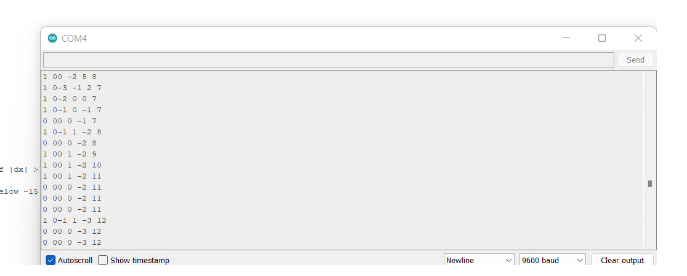
Now upload the code by selecting the right port and board and then press the boot button to bring the ESP32 board into boot mode to upload the code.
Now after uploading the code, open the serial monitor and then move the hand or object in the front optical flow sensor, it will show you the motion and the displacement data in the x and y-axis in the serial monitor.

Sir, can I use Arduino UNO instead of ESP32?
yes why not , but you need to change the code to use Arduino pins configurations