


Here we design a simple and small project that is portable power supply (voltage regulator). We know that all electronic devices require DC power supplies. And usually at our homes, the AC power supply is coming, that is 230 volt, 50 Hertz AC supply. We need to convert this AC supply into a DC supply.
Normally, the electronic gadgets operate on 5V DC, otherwise 9V, 12V volt DC and 8V DCs are also required for different applications. But it is very complex to carry the power supply with us always. So here there is a small solution with a very simple arrangement. We can design the circuitry and assemble it in a very small box that we can easily carry.
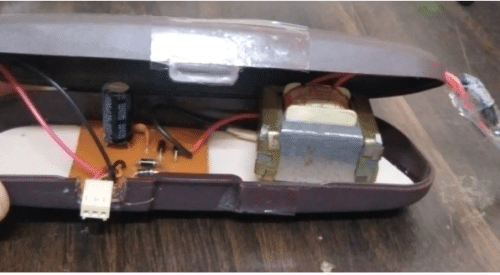
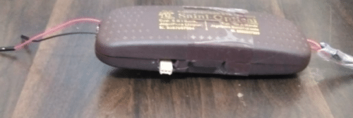
Here to make it portable we use a sunglasses case (specs box) so as to make it simple to carry. We assemble the whole circuit in this sunglasses case. We design the layout of the voltage regulator in Proteus software, then assemble the component and do the soldering and finally assemble in sunglasses case.

We can easily use this circuitry and bring this circuitry with us, wherever it requires. There are different voltage regulator IC’S available such as IC-7805 for +5 volt DC, 7808 for +8 volt DC,7809 for +9 volt DC, and 7812 for +12 volt DC and similarly 79xx Series for negative voltages. So according to the requirement we have to connect only a particular regulator IC in 3-pin female connector socket so that we wil find the output.
Advantages of Proposed Prototype
1. Reduce the complexity to carry power supply section.

2. We can use different output D.C voltage according to different need without altering the circuit connection and soldering.
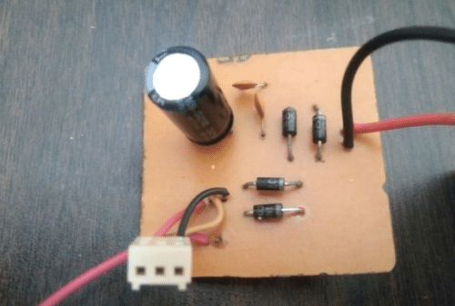
Parts List
| Name | Quantity |
| 12V TRANSFORMER | 1 |
| 7805 /7809/7808 IC | According to use |
| 1000µF,63V CAPACITOR | 1 |
| 0.1µF CAPACITOR | 2 |
| 1N4007 | 4 |
| Two pin cable/three pin cable | 1 |
| 3-pin female connector base | 1 |
| Sunglasses case | 1 |
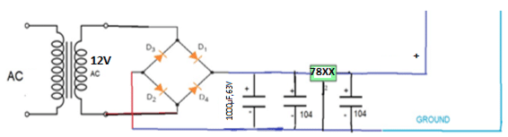
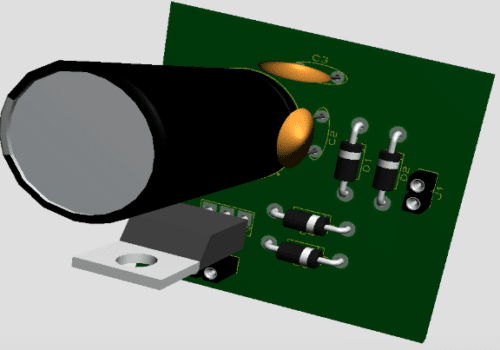
The circuit diagram of the power supply section is shown in figure-1.
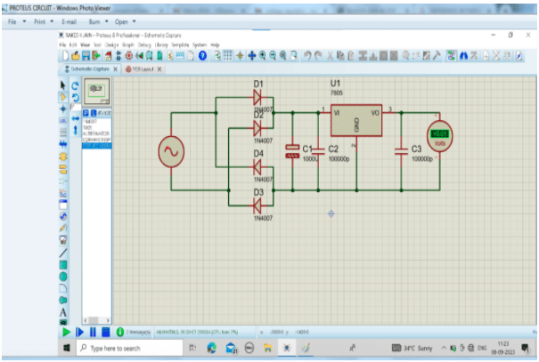
First we design it on simulation environment i.e. on proteus software to check the result.So for it we design a +5V circuit on proteus here instead of transformer we use an alternator to give 12V ac input as in Fig. 2.
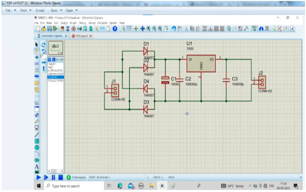
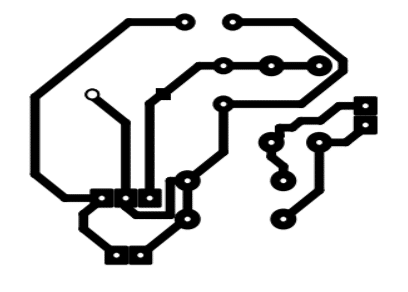
Before finding out the layout of schematic circuit of Fig. 2 we replace the input alternator and output DC voltmeter by two 2-pin connector so in layout they can automatically represented as in Fig. 3.

Rakesh Jain received Master degree in VLSI, B.E. in ECE, DIPLOMA in electronics. He is currently working as an Assistant professor in ECE department in Geetanjali institute of technical studies, Udaipur. His research area is SENSOR and Microcontroller. He has 26 copyright and 3 Indian patents. He has also been honoured with Mewar Scientist Award2023.
