This circuit can be used for making a beautiful light for your Christmas star or Diwali lanterns for your festive evening.
The speciality of this light is that its brightness increases gradually and once it reaches the brightness peak, it gradually decreases and so on, this cycle repeats until it is switched off.

Apart from the making of the circuit, this article will also help a beginner to understand about 555 IC, astable configuration, BC 547 NPN transistor switch, working of an Opto-coupler, switching of a TRIAC etc. The main components of this project are 555 IC and optocoupler MCT2E. IC 555 is configured in astable mode and the discharge pin (Pin number 7 )is open. Pin number 2 and 6 are combined with each other and at that point, output pin 3 is connected via a Resistance R1, so that the capacitor C1 gets charged and through R1 (3 is the output of 555 ) and discharging of C1 will trigger the pin number 2. ON time and OFF time can change either by changing the values of R1 or C1. Please refer the Datasheet for the pin diagram of 555 and refer the astable, monostable circuits. This project can also be constructed with BC547 astable multivibrator circuit.
Components Required
- IC1- 555
- IC2- MCT2E
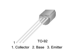
- TR1 – BC 547
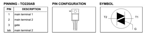
- TR2 -Triac BT136
- D8- Diac DB3
- D4, D5, D6, D7 – IN4007
- LED 1, 2 – Red or any desired colour
- R1 – 33K
- R2 – 10K
- R3 – 22K
- R4 – 100 Ω
- R5 – 270K
- Vr1 -1MΩ use 1M (Volume control pot)
- C1 – 47 MFD 25V
- C2 – 1000 MFD 25V
- C3 – .1 MFD 400V
- Fuse – 1.5 A
- Electric Bulb 100W 250V
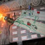
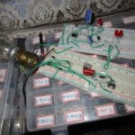
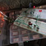
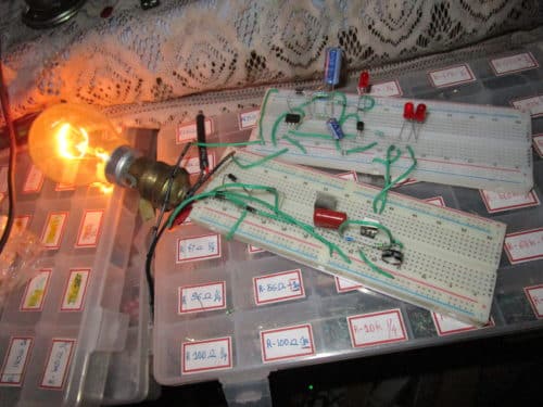
Construction & Testing
MCT2E Schematic
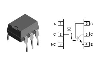
- Pin 1 – Led Anode
- Pin 2 – Led Cathode
- Pin 3- NC
- Pin 4 – Emitter
- Pin 5- Collector
- Pin 6- Base
BT136
BC547 NPN Transistor
Circuit Description & Working
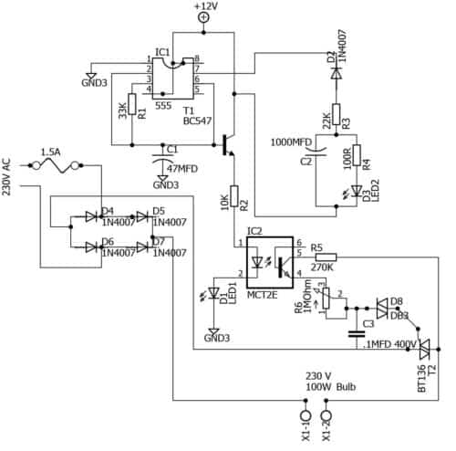
Pin number 1 of 555 IC is ground and 4,8 is +VCC. 555 IC can work from 4.5 to 16 v as per the datasheet. This circuit is the same as the astable multivibrator circuit given in the datasheet. Only difference that the trigger capacitor is using Output pin 3 to charge and trigger the IC and pin number 7 (7 is a discharge pin of 555 which will give ground supply with respect of triggering frequency) is opened and given this to a RC parallel circuit from which we can understand that the IC is triggering with the help of LED 2 . While switched ON, the Capacitor C1 gets charge via Pin number 3 through the resistor R1, where the base of a BC547 also connected for switching the LED 1 and optocoupler input. BC 547 acts as a transistor switch. BC 547 requires 0.05mA and 0.70 V at the base pin for start its conduction from collector to emitter, till that the transistor remains off. Due to the presence of C1 in the base, the voltage will increase gradually only with respect to its charging time. Once the capacitor charged it will start to discharge then pin number 2 of 555 will get a trigger gradually tr1 turnoff. This will make the transistor and the LED optocoupler input gradually faint off. This process will continue automatically.
Note: On time and off time can change either changing the value of C1 or R1.
Pin number 7 of 555 IC will get the ground supply from the triggering frequency at pin 2. In this circuit, this ground pin has taken out from the circuit using IN4007 (D2) and R3 22k to an RC parallel network where LED2 (D3) is connected. This RC parallel circuit will also give ON and gradual OFF effect with respect of resistance and capacitor value. C2 in the RC parallel circuit has 1000mfd 25 v and R4 has 100 ohms. These Led 1 and 2 in the Primary section can be used to troubleshoot once the circuit is not working. Moreover, a beginner can get the idea of how RC parallel circuits work from the blinking of LED2.
Note: If LED 1 is ON permanently and LED 2 is not, then the problem is with the 555 IC.
If lED 2 is ON and goes gradually OFF but 1 does not, there might be a problem with the transistor BC547 or R2 10 K.
Current flowing through the collector to emitter = base current x current gain.
Here in BC547 has a current gain of 200 then current through the collector to emitter = .05 X 200 = 10mA, This means collector to emitter has 10mA while the base has .05mA.
The secondary section of this circuit is interfaced with primary using Opto coupler MCT2E which has a phototransistor at the output. Once the internal LED is ON and when its light hits on the phototransistor, it will start to conduct collector to emitter. The collector to emitter maximum current flow is 150mA and maximum collector to emitter voltage is 30V which is controlled by resistor R5 (Collector resister) which has a value of 270K. At the emitter section, a variable resistance VR1 of 1Mega Ohm is connected and (to reduce the current flow in the DIAC ) it will help to adjust the light’s minimum brightness level. A DIAC DB3 has been connected to the gate of BT 136. Capacitor C3 is 0.1Mfd and 400V act as snubbing circuit for Diac DB3. For better result use 0.1mfd (104) 400 V capacitor. While Db3 gets 30V (nearly 27 ), it will start to trigger the TRIAC BT136. On getting a trigger, TRIAC T2 will conduct from MT2 to MT1 so the bulb will get illuminated. Since this circuit is triggering and operating on the minimal triggering voltage and current, it will give a gradual, on and faint off effect at the electric bulb.
If the resistance VR1 is too high the lamp may flicker or remain OFF, adjust the VR1 to adjust the brightness of the lamp. When supply voltage varies, you have to adjust potentiometer VR1 as stated above, for the proper performance of the circuit.
If you want to connect more bulbs, connect it serially and make sure that the current capacity of TRIAC and rectifier diode also withstands it. This circuit can be constructed with SCR also but mind the polarity to connect in the circuit. (SCR will conduct only one direction but TRIAC will conduct in both) IN4007 will give 1A output for the circuit. X1-1 and X1-2 are the terminal connection for connecting the light bulb serially with the circuit. Solder the components and enclose in a box to prevent electrocution. Fix the 1 Megaohm volume control pot on the box so that you can adjust the light through the safer side.