 Very-large-scale integration (VLSI) is the technology of creating an integrated circuit (IC) by blending billions of transistors on a chip. VLSI began in the 1970s when complex semiconductor and communication technologies were being improved. The microprocessor is a VLSI appliance. Before the initiation of VLSI technology most ICs had a restricted set of functions they could execute. An electronic circuit might contain a CPU, ROM, RAM and further glue logic. VLSI lets IC designers add all of these into single chip.
VLSI (very large-scale integration) is the current level of computer microchip miniaturization and alludes to microchips containing in the hundreds of thousands of transistor s. LSI (large-scale integration) meant microchips including thousands of transistors. Former, MSI (medium-scale integration) meant a microchip including hundreds of transistors and SSI (small-scale integration) meant transistors in the tens.
Network on chip or network on a chip (NoC or NOC) is a communication subsystem on an integrated circuit (commonly described a “chip”), usually among intellectual property (IP) cores in a system on a chip (SoC). NoCs can span synchronous and asynchronous clock domains or use unclocked asynchronous logic. NoC process applies networking concept and techniques to on-chip communication and brings remarkable improvements over conventional bus and crossbar interconnections. NoC increases the scalability of SoCs, and the power effectiveness of complex SoCs associated to other designs.

The wires in the connects of the NoC are shared by several gestures. An elevated level of parallelism is achieved, because all links in the NoC can operate simultaneously on various data packs. Therefore, as the difficulty of integrated systems keeps developing, a NoC grants enhanced performance (such as throughput) and scalability in comparison with prior communication architectures (e.g., dedicated point-to-point signal cables, shared buses, or segmented buses with bridges). Of course, the algorithms should be designed in such a way that they offer great parallelism and can hence employ the potential of NoC.
Benefits of NoCs
Customarily, ICs have been designed with dedicated point-to-point links, with single wire dedicated to every signal. For huge designs, in specific, this has several restrictions from a physical design point of view. The wires involve much of the region of the chip, and in nanometer CMOS innovation, interconnects dominate both performance and energetic power dissipation, as signal propagation in cables across the chip needs manifold clock cycles. (See Rent’s rule for a discussion of wiring requisites for point-to-point connections).

Working Mechanism
NoC with concurrent aid, that provides solid bounds on both (1) in-flight NoC routing latency due to deflection, and (2) the source queuing waiting time at the source node. A 64b HopliteRT router implementation delivers almost identical LUTFF cost (2% less) connected to the original Hoplite router. We also combine two counters to the client interface to offer a Token Bucket observe for monitoring package injection in a manner that bounds source queueing delay. We exhibit the inflight NoC routing bound to be (ΔX +ΔY +(ΔY ×m)+2), and the source-queueing bound to be(1ρi−1)+Ts:Ts=σ(ΓCf)1−ρ(ΓCf) We test HopliteRT across several numerical datasets and exhibit that (1) our exploratory bounds are relatively tight for RANDOM workloads, and (2) our solution supplies significantly better latency behavior for ALLTO1 workload that replicas shared DRAM interface access.
We instigate HopliteRT (Hoplite with Real-Time extensions) that needs no extra LUT resources in the router and just two cheap counters in the client/processing constituent.
These alterations implement the newest routing logic and pack regulation policy in the system. The router mutation has a zero price overhead over baseline Hoplite due to a just re-encoding of multiplexer select signs that drive the switching crossbars. With cheap counters at the client injection port, we can enforce a token bucket injection policy that controls the burstiness and throughput of the several packet flows in the system.
module DE1_NOC_PWM(
/// CLOCK //
input CLOCK_50,
input CLOCK2_50,
input CLOCK3_50,
input CLOCK4_50,
/// SEG7 //
output [6:0] HEX0,
output [6:0] HEX1,
output [6:0] HEX2,
output [6:0] HEX3,
output [6:0] HEX4,
output [6:0] HEX5,
/// LED ///
output [9:0] LEDR,
/// SW //
input [9:0] SW
);
endmodule
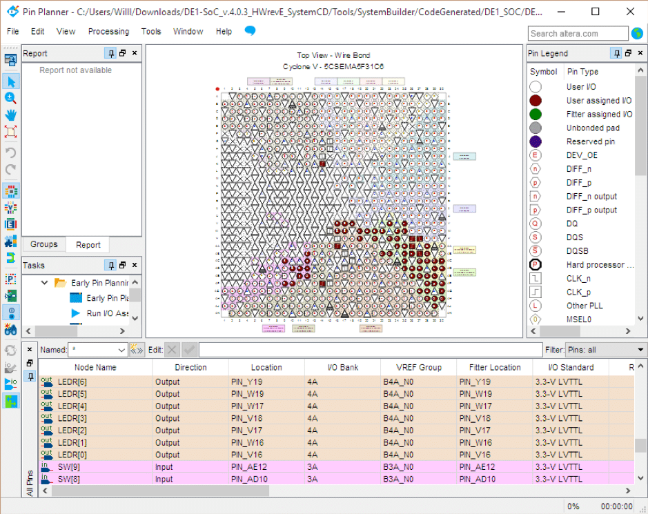
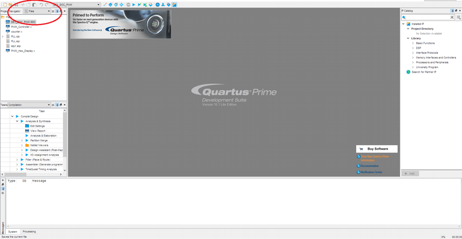
We can see that the stick assignments for the inputs and outputs in the top file have been done for us. This is one of the advantages of the utilizing the system builder software, as this move can be quite extensive and tedious.
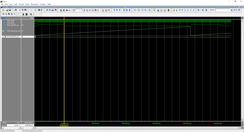
RTL Simulation
The ModelSim Altera Edition software will be utilized to perform the RTL simulation of the PLL. Before this can be complete, a test bench is necessary. A test bench is parallel to the top file, but is utilized for verification.
Design a fresh project in ModelSim, and compose it the equivalent directory as the Quartus project file. Add the existing PWM driver and counter elements and compile them. Add a recent verilog file to the similar directory and call it [module_under_test]_tb.v. `timescale 1ps / 1ps
module PWM_tb;
reg clk;
wire PWM_out;
wire [7:0] counter_out;
reg [7:0] PWM_CW;
assign counter_out = PWM_inst_1.counter_inst.counter_out;
parameter CYCLE = 200000;
parameter HALF_CYCLE = 100000;
initial
begin
clk=1’b0;
PWM_inst_1.counter_inst.counter_out=8’b0;
PWM_CW=8’b00110000;
end
always
begin
#CYCLE clk = !clk;
end
PWM_Controller PWM_inst_1 (
.clk (clk),
.PWM_CW (PWM_CW),
.PWM_out (PWM_out)
);
endmodule