


 In this project, we look to solve the problem of the number of appliances being operated using a microcontroller. Generally, this number is restricted to 3 or 4, with this project in action, it can be increased up to 1 appliances. When we make appliances control by RF (ASK) module we control only 4 appliances, but we can control up to 16 appliances because the ICs used in transmitter and receiver sections (HT12E & HT12D) convert BCD parallel data into serial data.
Since it can take BCD input, we can give 24=16 different type of input and it can be decoded at the receiver section very easily.
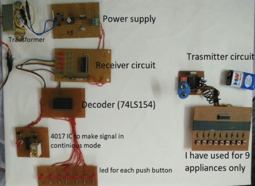
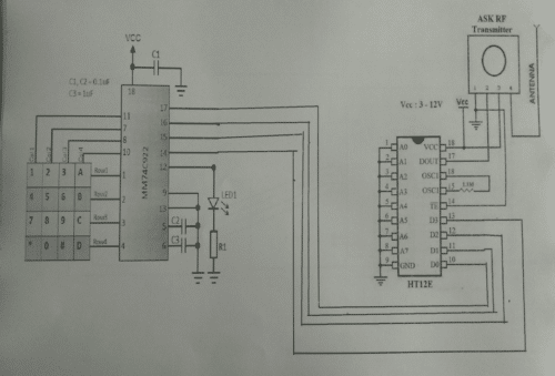
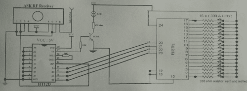
At transmitter section, we have used 74C922 IC to get BCD output on pressing any button of the keypad matrix and at the receiver section, we use 74LS154 IC to decode each BCD code into the corresponding output.

Component Required For Transmitter
| S.NO. | COMPONENT NAME | QUANTITY |
| 1 | 4*4 matrix keypad | 1 |
| 2 | 74C922 IC | 1 |
| 3 | 0.1 uf capacitor | 2 |
| 4 | 1 uf capacitor | 1 |
| 5 | Led | 1 |
| 6 | Resistor(330ohm) | 1 |
| 7 | HT12E IC | 1 |
| 8 | RF(ASK) TRASMITTER | 1 |
| 9 | Resistor(1.1M) | 1 |
Component Required For Receiver
| S.NO. | COMPONENT NAME | QUANTITY |
| 1 | Ask RF Receiver | 1 |
| 2 | HT12D IC | 1 |
| 3 | Resistor(51K) | 1 |
| 4 | Resistor(10K) | 1 |
| 5 | BC548 transistor | 1 |
| 6 | Resistor(470ohm) | 1 |
| 7 | Led | 17 |
| 8 | 74LS154 IC | 1 |
| 9 | Resistor(330 Ohm) | 16 |
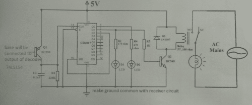
Since the signal received at the receiver is active low, till the push button is pressed at the transmitter section, to control appliances by this signal we must make another circuit that will convert the single pulse into a continuous form. This will be used to drive relay and control the appliances.
Components required for stable multivibrator
| S.NO. | COMPONENT NAME | QUANTITY |
| 1 | 4017 IC | 1 |
| 2 | BC558 transistor | 1 |
| 3 | 0.1 uf capacitor | 1 |
| 4 | Resistor(220K) | 1 |
| 5 | Resistor(470 ohm) | 2 |
| 6 | Led | 2 |
| 7 | Resistor(1K) | 1 |
| 8 | BC548 transistor | 1 |
| 9 | IN4007 diode | 1 |
| 10 | Relay(5v,100 ohm) | 1 |
Circuit operation
- When we press any button, the 74C922 IC converts that signal into BCD parallel form.
- HT12E encodes that parallel BCD data into Serial data, which is then given to RF transmitter module for transmission.
- The RF receiver module receives that data and sends it to HT12D. It converts that data from serial to parallel (BCD conversion).
- 74LS154 IC (4*16 decoder) decodes the BCD data into its corresponding signal.
- A bistable multivibrator circuit is connected at each output of 74LS154 IC. This will convert the signal into a continuous form.
