


 Presented here is a submersible pump starter circuit using electronic overload relay, solid-state relay and adjustable startup delay.
A submersible pump is a type of centrifugal pump designed to function with the pump and the motor completely submerged in the water. The motor is sealed in such a way that it prevents any ingress of water from seeping into the motor casing and causing it to fail.
Since the pump is submerged in water, floor space can often be better utilised. Overall cost of the installation can also be reduced. This type of pump tends to have lower maintenance cost and creates less noise than a pump installed above ground.

 Capacitor-start and capacitor-run motors are widely used in submersible pumps. These are used in a wide range of single-phase applications primarily for starting hard loads. These motors have moderate-to-high starting torque compared to other types of single-phase motors. Starting torque generally ranges from 200 to 350 per cent of normal full-load torque.
The main advantage of a capacitor-start motor is the lower starting torque, which results in lower starting current. This motor is generally used for single-phase applications between three and 10 horsepower.
Since the pump is submerged, there are no issues with pump priming either. But fixing a centrifugal switch and capacitor inside the motor can be dangerous. So, capacitors are fixed inside the control panel. The most complicated part in this system is replacing the inbuilt mechanical centrifugal switch with an external electronic centrifugal switch.
In the older version of the starter, centrifugal cut-off is achieved manually by pressing and releasing a pushbutton switch. But in the latest version, automatic switch operations and delays are provided. The control panel should be a foolproof system to protect the motor from any damage.
Main disadvantages of starters used in older submersible pumps are as follows:
- Electromechanical relays employed have a limited operational life.
- Mechanical overload trip mechanisms have less sensitivity.
- Startup time delay cannot be changed.
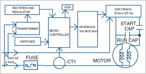
This project solves the problems of existing submersible motor starters by using an electronic overload relay, a solid-state relay in place of an electromechanical relay and an adjustable startup delay. Fig. 1 shows the block diagram of the project.
Circuit and working
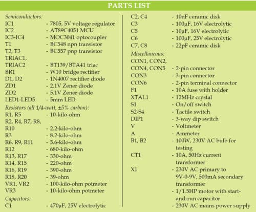
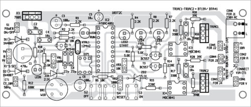
Fig. 2 shows the circuit diagram of the submersible motor control panel. The circuit is built using 7805 regulator (IC1), microcontroller (MCU) IC AT89C4051 (IC2), two BT139/BTA41 triacs, two triac driver ICs MOC 3041 (IC3 and IC4), three transistors (T1 through T3), 10A, 50Hz current transformer (CT1) and a few discrete components.
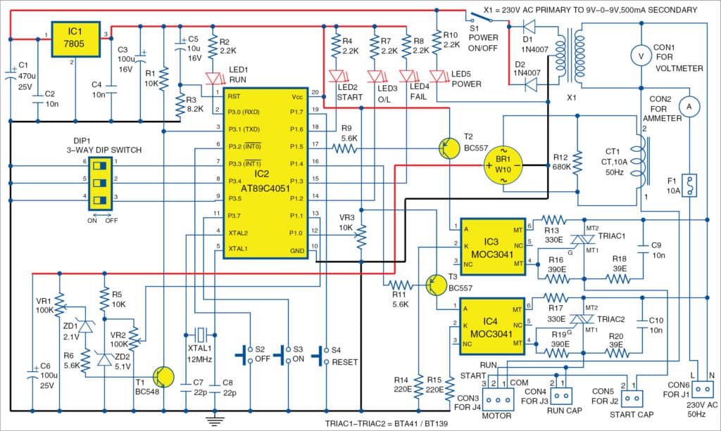
The circuit is powered with 230V AC mains. Transformer X1 steps down voltage to 9V-0-9V. Diodes D1 and D2 act as rectifier diodes, and capacitors C1 and C2 are connected as filters. Rectified DC voltage is regulated to 5V using IC1 and fed to MCU circuit.
The heart of the circuit is the MCU IC AT89C4051 running at an oscillator frequency of 12MHz, by connecting crystal XTAL1. Power triacs BT139 are interfaced to the MCU through triac driver ICs and transistors.
AT89C4051
AT89C4051 is a low-voltage, high-performance CMOS 8-bit microcomputer with 4kB flash programmable and erasable read-only memory (PEROM). The device is manufactured using Atmel’s high-density, non-volatile memory technology. It is compatible with industry-standard MCS-51 instruction set.
By combining a versatile 8-bit CPU with flash on a monolithic chip, AT89C4051 becomes a power-full microcomputer that provides a highly-flexible and cost-effective solution to many embedded control applications.
For details on AT89C4051 MCU, refer to the its datasheet on their website.
Switch S1 is used to turn on and turn off the power to the circuit. Capacitors C2 and C4 are used for suppressing high-frequency signals generated by the circuit. C7 and C8 are decoupling capacitors for crystal XTAL1.
Capacitor C5 and resistor R3 form power-on reset circuit for MCU IC2. S2 is used to stop, and S3 to start the motor. S4 is used to reset the system from overload or motor failure condition.
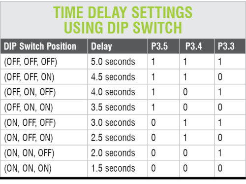
PCB-mountable DIP switch (DIP1) is configured to get the required startup time delay. Total eight timing delays can be configured by adjusting switch positions. The table shows the delay against each configuration.
LEDs (LED1 through LED5) are used to indicate the various statuses of the system. Current transformer CT1 senses the motor current. Bridge rectifier BR1 rectifies CT1 output to DC, and C6 acts as a filter to smooth DC output of the rectifier.
VR1 can be used to set overload current value. A combination of ZD1, R6, T1 and R1 is used to provide motor current signal to the MCU.
One of the special characteristics of CT1 is that it burns out if connected without output load. Resistor R12 (680kW) connected across it is absolutely necessary to safeguard CT1.
Transistors T2 and T3 work as output drivers for optocouplers MOC3041. IC3 and IC4 optocouplers are used as triac drivers. IC3 and triac1 form the first solid-state relay (SSR1), and IC4 and triac2 form the second solid-state relay (SSR2).
Software
The software (subpump.c) is written in C language and compiled with Keil µvision 4 software. Logic behind the software is described briefly for better understanding.
 One of the most important features of AT89C4051 is the inbuilt analogue comparator. This special feature of 8051 family chip is not utilised widely. In this project most of its special features, such as inbuilt comparator, internal timer and external interrupt, have been enabled.
In the main part of the software, the MCU scans the status of DIP1 and stores the corresponding startup delay. On pressing S3, the software activates both solid-state relays to connect the power supply to the motor through start-and-run capacitors.
The software monitors the current output from CT1. If current is less than the set value, it assumes that the motor is delivering very low current. Connections will not be successful if current is low. The software deactivates all outputs (pins 16 and 17 of IC2). The motor pump stops working, and motor failure indicator gets turned on.
If current output is found normal, the system switches off the start winding output after a set delay. The motor pump keeps running, and motor current output is monitored from CT1.
If motor current is found more than the overload set value and the same condition stays for a predetermined time, overload condition gets activated and all outputs are deactivated. The motor pump stops.
Internal timer function is used to get accurate long delay, and interrupt function is used for switching off the motor at any time without any delay. Reset switch (S4) can be used to break error loops of the software.
Construction and testing
An actual-size PCB layout of the submersible pump starter control panel is shown in Fig. 3 and its components layout in Fig. 4.
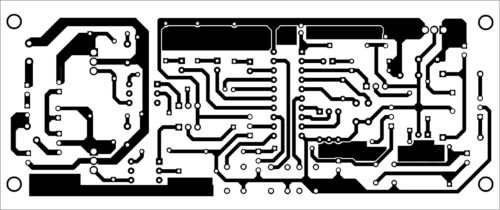
Download PCB and Component Layout PDFs: Click here
After assembling the circuit on the PCB, burn the hex code into the MCU AT89C4051 and insert it into the socket, connect 230V across CON6 and the primary of X1. Solder the coil of CT1 on the PCB and pass the mains live (L) wire inside CT1 after fuse via points 1 and 2, as shown in the PCB.
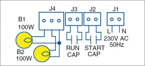
For testing the working of the circuit, connect two 100W, 230V AC bulbs at J4. Connect run-and-start capacitors, as shown in the wiring diagram in Fig. 5. If the motor has only one capacitor, refer to the technical manual of the motor to confirm its type, and also check the type of capacitor used.
When S1 is closed, LED5 will glow. Adjust DIP switch DIP1 to get three seconds delay as per the table. Press S3 (on) momentarily, and LED1 will glow. Lamps B1 and B2 connected at J4 will also glow at almost the same brightness. After three seconds, one lamp connected to J4 will become dim.
Adjust VR2 slowly and wait for three seconds till LED4 lights up and LED1 goes off. Ensure that both lamps connected at J4 are off. Turn VR2 in one direction and press S4 momentarily. Press S4, and LED1 will light up. Both lamps connected at J4 will also light up at almost the same brightness. After three seconds, one lamp connected to J4 will become dim.
Ensure that the system stays in this condition for more than two minutes. If not, repeat the same process by varying VR2 as in last rotated direction.
Rotate VR1 fully in clockwise direction. Wait for one minute for LED3 to light up, and LED1 and LED2 to go off. If that does not happen, rotate VR1 fully in anticlockwise direction, and repeat the same process. Rotate VR1 slowly in reverse direction and ensure that the system stays in on condition for more than two minutes.
In brief, at normal condition, keep around 0.45V at pin 12 of IC2 and 0.9V at pin 13 of IC2, using VR3 and VR2, respectively. Also, when normal current is flowing through CT1, pin 3 of IC2 remains low. This becomes high when higher current flows through CT1.
After proper calibration, fix the entire assembly in a suitable enclosure and connect the motor after removing the bulbs.
Switch on the unit and ensure that water is flowing from the pump, and current and voltage indications are normal. Adjust VR2 slowly to hold the system in normal condition without an overload trip.
Download source folder
Asokan Ambali is working as senior instrument mechanic at Naval Aircraft Yard Kochi
