


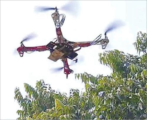
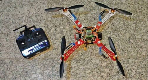
 Small drones are being used to deliver parcels, for videography of events such as marriages, and surveillance of enemy territory. You can make a drone at home without spending a fortune. Presented here is a low-cost quadcopter drone using an F450 frame and brushless DC motors. The author’s prototype is shown in Fig. 1.
To make the drone, you need to collect the components listed in Table 1. You may also need jumper wires and connectors for the circuit and battery.

Before jumping to construction and assembly of the project, you need to know some basic things about the drone including its propellers, motor rotation, transmitter, and receiver.
Propellers
The propellers come with numbers marked on them, starting with either R or L letter and, sometimes, without any letter. If the number starts with R, it means right or clockwise rotation. If the number following R is 1045 (like R1045), the first two digits (10) indicate length of the propeller in inches (10-inch or 25.4cm in this case). The next two digits (45) indicate the pitch (4.5-inch or 11.43cm) the propeller cuts through the air per revolution.
If the number on propeller starts with L, it of course means the propeller is meant for anti-clockwise rotation. In this project, two propellers are for clockwise rotation and two for anti-clockwise.
With increase in pitch, the thrust provided by the propeller also increases. But that requires higher torque from the motor. So, you need to maintain the right balance between motor and propeller configurations.
Motors
In a quadcopter drone, two DC motors are required for clockwise rotation and two for anti-clockwise rotation. A suitable propeller is attached to each of the motor.
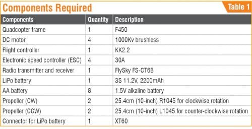
For the quadcopter to fly, each propeller’s rotation should provide sufficient thrust to lift the drone. To achieve this, the motors need to be setup in the following manner:
- Front left motor should rotate clockwise (CW)
- Front right motor should rotate counter-clockwise (CCW)
- Rear left motor should rotate counter-clockwise (CCW)
- Rear right motor should rotate clockwise (CW)
So, we need to install the motors and propellers accordingly as shown in Fig. 2.
Electronic speed controller
Each motor in quadcopter is attached to a circuit called electronic speed controller (ESC). The quadcopter’s flight controller sends information to the motors via ESC. Each ESC module must be rated at least 10A more than the motor. Suppose your motor is going to consume 20 amperes on full throttle, then the ESC should be rated 30A or more.
The Kv rating of motors refers to the constant velocity of a motor (it is not kV for kilo-volt). Low Kv rating means a lower rpm of the motor. This means a longer propeller would be required to get sufficient thrust to lift the drone. With higher Kv rating of the motors, smaller propellers can be used.
In this project, 1000Kv brushless motors are used along with 30A electronic speed controllers. Since Kv rating is low, we need at least 25.4cm propeller to lift the F450 drone body easily.
In case a smaller drone frame like QAV250 is used with smaller 12.7cm propellers, the same motors will not be able to lift of the drone. To get adequate amount of thrust from these propellers, we will need higher Kv rating, such as 2000Kv, motors.
Radio transmitter and receiver
FlySky FS-CT6B transmitter and receiver set is used in this project. These are pre-programmed and pre-bound. If you wish to change the radio transmitter or receiver then you will need to bind them first.
Radio transmitter requires some settings/configurations to control the drone. First, you need to bind your transmitter to your receiver, which enables your transmitter to control the receiver and hence the drone. Binding steps and configurations are normally explained in the user manual.
Construction and assembly
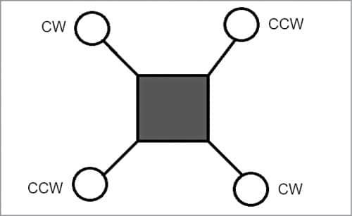
First screw in the four arms of quadcopter to the central frame as shown in Fig. 3. Solder the ESC to the frame power distribution circuit board. Mount the LiPo battery on the middle of drone frame. You may use insulation tape for this.
Now mount the KK 2.2 flight controller in the middle of the frame and fix it with adhesive as shown in Fig. 4. Next fix the motors on the arms with screws and attach all four ESCs to the arms. Attach the correct propellers to the motors.
ESC calibration
We need to calibrate all the ESCs so that all the motors start at the same time and get the top speed on full throttle. Most flight controllers have settings of their own for ESC calibration. Manual calibration for each ESC can be done using radio receiver and transmitter.
For calibration, connect a motor to ESC and then to channel 3 (throttle of RC receiver). Keep the throttle knob at maximum position on radio transmitter and turn on the transmitter. After that connect the LiPo battery and power on the ESC. Wait for two beeps and then move the throttle stick/knob to minimum position and wait for a few seconds till you hear three beeps. Then unplug and plugin the LiPo battery. Slowly move the throttle stick and the motors will start to rotate. With this, one of your ESCs is calibrated.
Repeat the same steps with all other ESCs one by one to calibrate them. The assembled quadcopter drone with ESC module mounted on each arm is shown in Fig. 5.
One end of each ESC has three wires for motor connections. The other end of ESC has five cables: two thick cables for power supply (black pin for GND and red pin for positive) and three thin cables for +5V supply, signal, and ground pins, respectively. Yellow cable is the signal pin for radio receiver’s channel 3.
On transmitter side, keep the throttle stick to low position and turn it on by connecting to the LiPo battery. (These steps require removal of all the propellers attached to the motors.) Then push the throttle stick slowly until you see the motor moving clockwise or anticlockwise. If it is clockwise, the motor should be at front left. Then swipe/interchange the two wires of ESC and check the reverse direction of motor. Repeat the same process with all the motors and make sure that the rotations of the motors are as per the directions shown in Fig. 2.
Now you may attach the propellers to the motors.
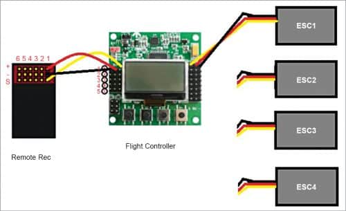
Connect yellow wire of each ESC to signal pin of flight controller. The connections between the ESC, flight controller, and remote receiver are shown in Fig. 6. Connect ESC1 through ESC4 to first row through fourth row pins of flight controller, respectively. Again, connect first row through fourth row pins of flight controller to first column through fourth column pins of remote receiver, respectively.
Flight controller settings
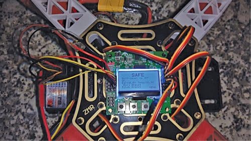
Next, we need to do some settings in the flight controller. First put the throttle stick down to minimum position and turn the RC transmitter on. Connect the battery to the drone and power the drone. Now the flight controller turns on and we can see the display showing either safety or error on the controller LCD.
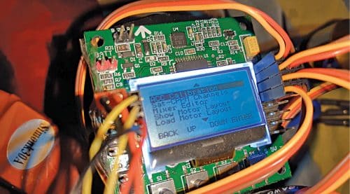
Using the buttons on the flight controller, as shown in Fig. 7, go to menu and select the Motor Layout type using Down button. Select the x quad motor layout, confirm the selection, and press the back button. Note that the flight controller unit should be attached to the F450 frame properly.

Accelerometer calibration
Put your drone on a flat surface, making sure the flight controller is stable and not tilted to any side. Press the menu button and using up/down button go to ‘Acc calibration’ option as shown in Fig. 8. Select the option and then press the select button again to continue. Wait for a few seconds for the flight controller to automatically calibrate the accelerometer and then show ‘ok to go’ on the display.
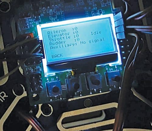
Flight controller uses signals from the radio receiver and passes these signals, together with stabilisation signals, to control the drone via the aileron, elevator, throttle, and rudder user inputs.
On the receiver side, check the rudder, elevator, throttle, and other values. If any value is more than zero, use the trim option in the remote transmitter. Trim the value to zero as shown in Fig. 9. Once the value gets trimmed, the drone is ready to fly.
Testing
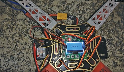
To start the flight, called arming, keep the throttle stick in transmitter to lower left for a few seconds and then increase the throttle slowly to full. The display will show Armed as shown in Fig. 10. The drone is ready to fly now.
To land the drone, decrease the throttle and disarm it by taking the throttle stick to lower right.
Ashwini Kumar Sinha is an electronics hobbyist and tech journalist at EFYi


Great article,
Please suggest a website to buy all the components required, at the cheapest price.
Thank you.
You can purchase components from Kitsnspares