


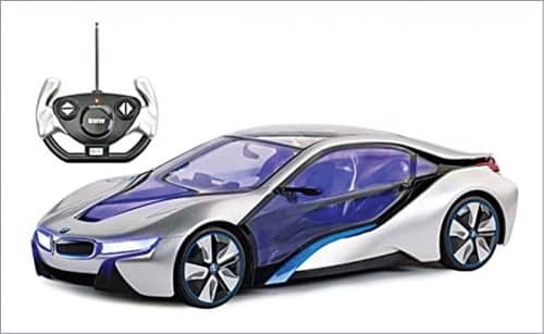
Remote controlled toy car features two small DC motors equipped with tiny gearboxes—one to spin the rear wheels and the other to steer the front wheels. Communication between the car and its handheld remote control is through a 27MHz radio link. A typical toy car with 27MHz remote control is shown in Fig. 1.
Table of Contents
Transmitter Circuit Design in 27MHz RC Toy Car Remote Control
Let’s start by looking at the transmitter circuit located inside the remote control, which is shown in Fig. 2. This circuit operates on a 3V battery.
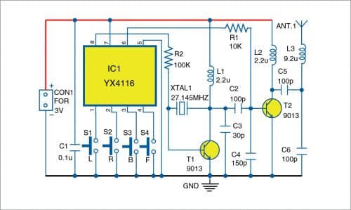
At the heart of the radio transmitter circuit board is the 8-pin encoder chip YX4116 (IC1). The rest of the electronics is a 27MHz radio frequency transmitter wired around two transistors and a handful of passive components.

There are four control buttons in the 3V (two 1.5V AA battery cells) DC powered transmitter board for left, right, back, and front movement. Now let’s take a look at the schematic of the radio transmitter board QF-1694-5T.
Here, the 27MHz carrier signal is generated by the oscillator comprising XTAL1, transistor T1, and inductor L1. Resistor R2 sets the bias current of T1 to excite the 27MHz (actually 27.145MHz) crystal and gets it oscillating at its natural frequency.
The encoded data signal on pin 6 of IC1 is coupled with the carrier frequency signal through resistor R1. The mixed signal then travels to the next stage formed by transistor T2 and inductor L2, and finally to the air through a piano-wire antenna.
The output is AC coupled through capacitor C5 to remove any remaining DC components. The L3-C6 network is used for impedance matching of the antenna. The 27MHz transmitter is turned on/off by the data (and control) signal from IC1.
Because of this active state the output is sinewave and the spacing between on/off transitions is in tune with the signal input from the encoder chip. Circuit diagram of the receiver in 27MHz toy car is shown in Fig. 3.
Receiver Circuit Components and Functions in Remote-Controlled Toy Car
Circuit of the 4.5V battery (three 1.5V AA cells) powered radio receiver board QF-1688-R3 located inside the toy car is a bit more complicated as it also includes integrated H-bridges for driving the two DC motors. Core of the radio receiver board is 16-pin decoder chip TXM8D423C (IC1).
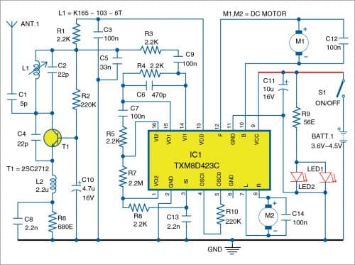
Front end of the radio receiver circuit is in fact a regenerative receiver that has been in use for decades. It is built around transistor T1. A tuned LC circuit (tank circuit) comprising L1 and C2 provides positive (regenerative) feedback but only at the tuned frequency of 27MHz.
Output signal from the tuned LC circuit is filtered to remove the carrier so that only data signal reaches IC1. Two standard H-bridge circuits inside IC1 are used for driving the propulsion motor for back and front (B/F) movement and the steering motor for left and right (R/L) movement.
The H-bridges allow smooth bidirectional control of the DC motors.
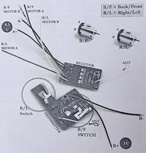
Fig. 4 shows the transmitter and receiver modules that are now available from many online shops as toy-grade replacement parts.
Assembly Instructions for Building an RC Toy Car
You can assemble the transmitter and receiver circuits on a general-purpose PCB. However, since 27MHz transmitter and receiver modules are now easily available in the market, their use would be a better option.
Connect the 3V battery to the transmitter module and enclose it in a toy car remote. Then connect the motors to the receiver module as shown in Fig. 4. Enclose the receiver in a toy car body.
Interested to explore more RC DIYs? Check out more RC projects here.
T.K. Hareendran is an electronics designer, hardware beta tester, technical author, and product reviewer

I need the PCB of this circuit to be shipped to my address. Is it possible to make the PCB and send the same?? I shall buy the electronic items and complete it at home.
The complete project kit including PCB, components and project manual can be made available. Please contact on [email protected] and also visit http://www.kitsnspares.com for more information on other projects.