


Power has very important requirement in human life. Every house hold equipment requires power to run Fridge, TV, Geyser, Microwave Oven, Induction Heater Water Pump even Mobile chargers, etc. whether mechanical power generated by an oil-engine or electrical power by a motor to run different types of machines. Oil is limited in natural stock & becoming costly as per huge requirement increases all over the world. The second option is Sun/solar power which are available unlimited in terms of light energy everywhere. A storage battery can be used & can be charged through solar panel to store electrical power for use when required. But it is a difficult task to use battery power directly to run a machine. Therefore, we have to convert DC battery power in to an AC power as per our requirement. An induction motor 3 phase is required to run a three phase 50 Hz power. In this project we are doing the same thing we are converting battery power in to 3 phase 50 Hz power with variable speed control. Attempting to this project it is very important to know the basic history and understanding of electrical power generation.
Electricity & AC Generation
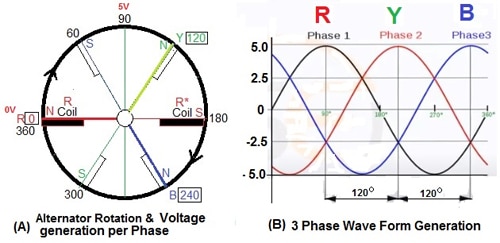
“Necessity is the mother of invention” it is very accurate in the sense of scientific inventions. After the invention of fractional electricity by a scientist named Benjamin Franklin in the year 1752 and another scientist Alessandro Volta invented electricity by chemical processes in 1799 with the help of two metal electrode Copper & Zinc with an electrolyte as sulfuric acid (H2SO4) to form a small 1.2 V DC power creator called a cell that later became famous after the name of scientist Alessandro Volta, VOLTA CELL and with the combination of cells developed the first electrical battery which was direct current (DC) battery. First of all, chemical energy is converted in to electrical energy by Volta after then Magnetic effect of electricity was observed by another scientist Nikola Tesla and he made an alternating current (AC) motor and developed AC generation and transmission technology. See (fig-1) to understand the basic of generator. At present, all the generators are working on the same theory & technology that is magnetic energy being converted in to electrical energy by mechanical power. But now it is possible, after the discovery of electron then semiconductor and later in the electronic engineering with solid state power switching devices to produce 3 phase ac power in static mode without any mechanical power. We can convert DC battery power in to AC power as per our requirement. Both single phase and three phases, same power is produced by either generator.
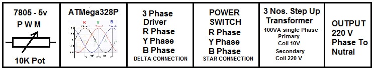
In this project we are also adopting the same theory & technology i.e. we are converting DC battery power in to AC 3 phase power by solid state power switching devices. We are producing static 3 phase signals with the help of ATmelga-328P. This is available in 28 pin DIL package we use this micro processor to generate static pwm R, Y & B phases. I preferred to use this Microprocessor ATmelga-328P because it is easily available with loaded boot-loader programmed in the local market and also available online on Amazon. A free platform is also available on internet to support programming of Microprocessors ATmelga-328P through ARDUINO IDE software specially to use boot loader programmed and other supported libraries for different uses of ATmelga-328P in other programmes. This project is very easy & can be understood through the block diagram as given in (Fig-2)

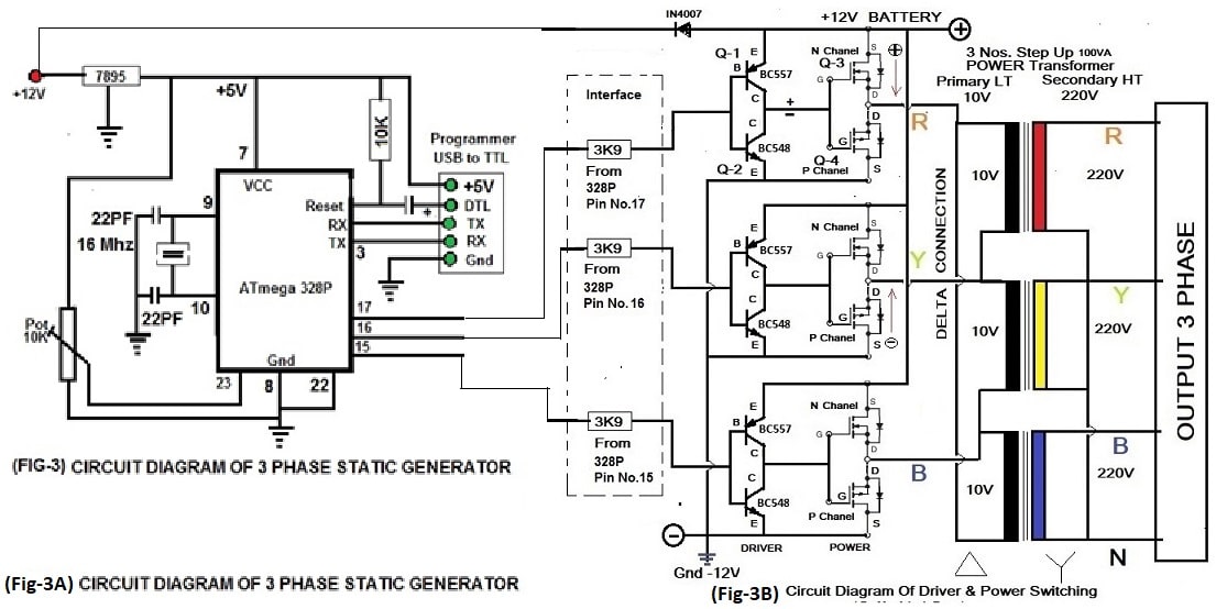
See Fig-3 the main hardware part of three phase static generator. The complete circuit diagram is given which is self explanatory.
Microcontroller Atmel-328
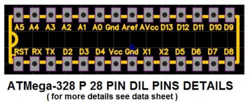
The heart of the 3 Phase Static Generator is a Micro Controller and the programming code Produces Sine wave 3 phase PWM at the output pins of Micro Controller. The three outputs of Micro Controller PWM interface with the hardware part through a resistance of 3k9 Ohms. As shown in Fig-3A & Fig-3B. Atmel-328 P 28 pin DIL package Pin details is given following.

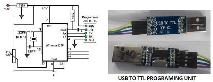
 Atmel328P is programmed through USB to TTL programming unit with ARDUINO IDE programming software. USB to TTL programming unit can purchase on Amazon. Connect USB to TTL programming unit with circuit as shown in fig-3 all connection as per circuit means +5V to +5v DTL to DTL TX to RX & RX to TX Gnd to Gnd. Then Run Arduino IDE Software goes to tool & Select Port and proceeds further.
Programming Code
The programming of micro controller Atmel-328 can be done through Programming software available on internet Free Public Platform Arduino. The Arduino IDE Software can be downloaded through this link (Support the Arduino IDE _ Arduino_) or Arduino IDE software is also attached here with for your ready use. Install Arduino IDE on your computer and then proceed as explained following.
Hardware Interface
Driver and Power Switching with Transformers
Here we have used four transistors per phase; two numbers as a driver & two numbers as Power Switching shown in Fig-3B. Transistor Q-1 is BC557 PNP small power common transistor, Q-2 is BC548 NPN small power common transistor both are used here as complementary pair. In the same way Q3- is N Chanel MOSFET & Q4- is P Chanel MOSFET transistor both are used as complementary pair. Power MOSFET Specification and number depend upon the output power requirement. You can also use paralleling of many same MOSFET to form an arm and use in place of Q-3 & Q-4 for higher power requirement. The DC power is converted here in to AC power through output MOSFET Power Switching System and fed to three numbers single phased Transformer whose primary is required as per Battery Voltage & secondary 220 Volts. In this practical project, we have used a very common transformer available in the market which is used in invertors whose primary is 10 Volts and Secondary is 220 Volts and the capacity is 100VA with Q-2 is IRF 9540 and Q-4 Is IRF 540. Transformer’s Primary coils are connected with each other in DELTA CONNECTION and Secondary coils are connected with each other in STAR CONNECTION as shown in circuit diagram Fig-3B.
 Programming process by Arduino IDE:
- Run Arduino IDE program on your computer by clicking Arduino Icon
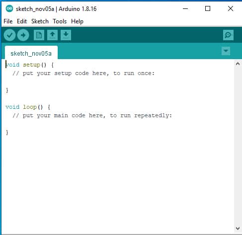
- Page will look like following
- Arduino new sketch page see Fig-4
- Select the following code then copy and paste on Arduino new sketch page
- Save the sketch page and type a name of your page
- Click on verify to check your saved page code
- Now connect USB to TTL programming unit to USB of your computer
- Put blank boot loaded Atmel 328 microcontroller chip on the socket 28 pin IC Chip.
- Now click on Upload
- After uploading the code Successfully
- Connect Hardware interface circuit to 3 Phase Static Generator Board
- Connect Battery
- Check voltage on each & every Transformer
- Increase & decrease potentiometer to check output voltage at transformers output end.
- Connect a small motor of 3 phase 220V 50Hz
- Change the speed of motor through PWM !0 K pot.
Code is also self-explanatory
// Three Phase Sine Wave PWM Generation by Mr.Adeeb Raza
// Programmed and TESTED OK by Mr. Adeeb Raza
// Basic Calculation as following
// Real Alternator Generate 3 Phase Supply, phase to phase 440 V AC 50 Hz
// Same 3 Phase Supply, phase to phase 440 V AC 50 Hz will produced with this
// Static Generator through this programming code with variation
// Frequency 50 Hz/Sec Or 1Hz = 1/50 Or 20 Mille Seconds or 360 degree = 20 mile sec
// 1 degree 20/360 = 0.05555 mille Second OR (1 mile Second = 18 Degree)
// Phase Angle difference 120 degree = 120/18 = 6.666 mille Second phase to phase
// Phase Angle Calculation in Radian where Pi=22/7 or 3.142 and one Radian=57.3
//*******************************************************************
#include <math.h> // Math Library for mathmatical calculation
int Output1 = 9; // Initialize arduino pin no. 9 as output for R Phase
int Output2 = 8; // Initialize arduino pin no. 8 as output for Y Phase
int Output3 = 7; // Initialize arduino pin no. 7 as output for B Phase
int potVal = 0; // Initialize Potentiometer 10K
float A = 0; // Analog 0 to 5V max = 0~255
float B = 0.104;
int Freq_IN = A0; // Analog A0 voltage as Frequency variation Input
int var1 = 0;
int var2 = 0;
int var3 = 0;
int var4 = 0;
int var5 = 0;
int var6 = 0;
float PhaseR = 2 * PI / 3; // 2*3.14/3 = 2.0952 (Sin120= 120/57.3= 2.094)
float PhaseY = 4 * PI / 3; // 4*3.14/3 = 4.1904 (Sin240= 240/57.3= 4.188)
float PhaseB = 2 * PI; // 2*3.14 = 6.2857 (Sin360= 360/57.3= 6.282)
//boolean toggle = true; // Serial Plotter Output
void setup()
{
Serial.begin(9600); // Serial Monitor
pinMode(Output1, OUTPUT); // R-Phase Output at Pin No.9
pinMode(Output2, OUTPUT); // Y-Phase Output at Pin No.8
pinMode(Output3, OUTPUT); // B-Phase Output at Pin No.7
pinMode(Freq_IN, INPUT);
}
void loop()
{
A += B;
analogWrite(Output1, var1); // Variable Output1 R Phase
analogWrite(Output2, var2); // Variable Output2 Y Phase
analogWrite(Output3, var3); // Variable Output3 B Phase
// if (toggle == true) // Serial Plotter Output
{
Serial.print(var1); // See Vlue on Serial Monitor or Check Wave Form on Serial Plotter
Serial.print(” “); // See Vlue
Serial.print(var2); // See Vlue on Serial Monitor or Check Wave Form on Serial Plotter
Serial.print(” “); // See Vlue
Serial.println(var3); // See Vlue on Serial Monitor or Check Wave Form on Serial Plotter in step
}
var4 = 126 * sin(A + PhaseR); // (0-253) Variable Voltage at R Phase
var1 = var4 + 128;
var5 = 126 * sin(A + PhaseY); // (0-253) Variable Voltage at Y Phase
var2 = var5 + 128;
var6 = 126 * sin(A + PhaseB); // (0-253) Variable Voltage at B Phase
var3 = var6 + 128;
if (A >= 2 * PI) // One Circle from 0 to 360
{
A = 0; // One Circle after 360 again start from 0
}
potVal = analogRead(Freq_IN); // Voltage variation PWM
delay(potVal);
}
//End Code

Is it possible to use IGBT in placed of power MOSFETs, if yes, then how to configure??
Author Adeeb Raza reply:yes you can use IGBT in placed of power MOSFETs, therefore I am attached here with the full circuit diagram for the same.
Explanation of Circuit is as following:-
Microprocessor 328P or Arduino Uno will be programmed to generate R Y & B signal to get output at pin no 9,10 &11 respectively Sine wave 3 Phase 50 Hz.
Signal Generated by Microprocessor at pin no 9,10 &11 respectively Sine wave 3 Phase 50 Hz, will be converted in to Positive & Negative phase switching for each phase through an inverter IC to ensure that only one transistor is conduct in a phase at a time .
The Positive & Negative signal of each phase send to optocoupler IC MET2E or 4N35 to switch IGBT driver IC IR2112 with full protection to drive Power Switching formed by IGBT in Bridge Configuration Circuit to produced High Current Power Output from 12 Volts Battery.
After these 3 Nos step-up Transformer Primary 10 V 10 Amp Secondary 220V will be connected.
Transformer Primary 10 V 10 Amp will be connected in delta connection while secondary will be connected in Star connection
Note :- we can also used this circuit in a different way also where we can generate 220 V AC Single phase Through a 12 V 120 AH Battery as used in Home Inverter. Inverter Output rectifies & filtered to get 350 Volts DC power Supply & then send IGBT Bridge Circuit to get 3 Phase R Y B Power to run an induction motor.
Regards
Are you available for hire to make this and ship to Bulgaria?
If so, is the frequency variable or can it be made so that it functions as a vfd?
What size is the final unit and how small can it be?
What are the amperage limits for the motor being supplied?
Thanks very much!