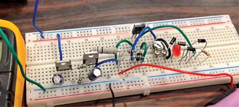
 This simple battery charger, with overcharge protection, can be used to charge multiple cells in a battery. It indicates when the cells are fully charged. The charger requires minimal components, which can be procured easily. The author’s circuit wired on a breadboard is shown in Fig. 1.
The circuit of the Li-ion battery charger, shown in Fig. 2, has three parts—charging and balancing circuit, current limiter, and constant voltage source. The circuit is capable of providing a maximum of 1.5A current and can take input up to 27 volts.

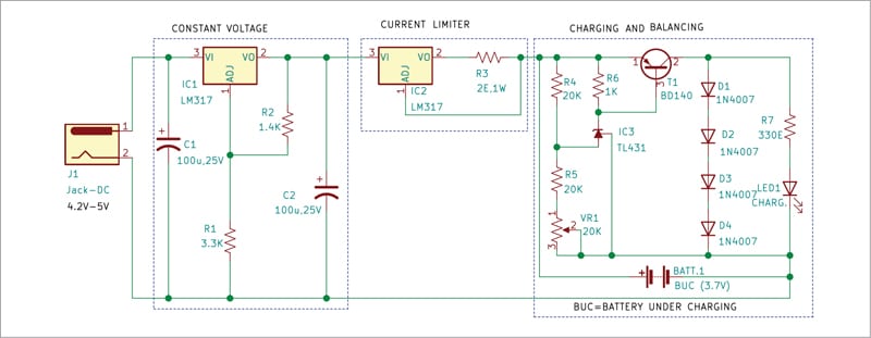
Charging and balancing circuit
When the voltage across Zener diode TL431 is below the threshold voltage, the Zener is in off state. Since the base of the transistor is connected to the cathode of TL431, the transistor remains in off stage as well. Therefore, the current flows through the battery, which is connected in parallel, and thus starts charging it.
On the completion of charging, when the voltage of the battery rises over the upper threshold voltage, the TL431 gets activated and connects the base of the transistor to the ground, thus turning the transistor to its conducting state. In this state, the transistor creates a new path for the current to flow, bypassing the battery, and so the charging stops.
The transistor is connected in series with four diodes, which act as a load. The diodes are also connected to a resistor and an LED in parallel to them. When the transistor is conducting, the current flows through the four diodes and the LED simultaneously, thus turning on the LED to indicate that the battery is fully charged.
The circuit also offers a cell balancing feature, which is important when we charge a battery with multiple cells in series. With the cells connected in series, we need to make sure that the total voltage of the battery pack after charging does not exceed the maximum specified voltage of the battery pack. Also, the voltage of each charged cell should not exceed the maximum specified voltage of that individual cell.
Current limiter circuit
Every cell has a maximum limit of charging current it can take, which is denoted by its C-rate. The C-rate of a cell depends on multiple factors, such as its chemistry, size, internal structure, etc. Charging with overcurrent may cause irreplaceable damage to the cell and may also cause thermal runaway in the battery, which can result in a fire. Therefore, IC LM317 is used as a current limiter.
As shown in Fig. 2, the voltage input pin VI of LM317 is connected to the positive of the source, and voltage output pin VO is connected to resistor R3. The adjust pin ADJ is connected to the other end of the resistor. The value of current I_out can be adjusted by changing the value of resistor R3, as per the relationship given below. Though, for this charger, we will keep the maximum output current (Iout) as 0.6A.
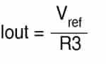
Here, Vref is 1.25V.
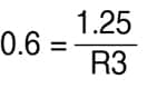
R3 is 2.08 ohm
Constant voltage source
To make the circuit more versatile and make it work over a wide voltage range, we employ voltage control by using another LM317 IC. The input terminal VI of this IC is connected to the ground through capacitor C1, which should be kept as close as possible to the input terminal. The adjust pin ADJ of the IC is connected to the Vout with resistor R2 in between and to the ground through resistor R1.
To improve the transient response of the output, capacitor C2 is connected across Vout pin of the IC and the ground. The output voltage of IC1 can be adjusted as per following relationship:
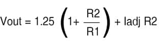
Since the value of Iadj is very small, it will have little effect on the output voltage. For a single cell Li-ion charger, the value of resistor R1 and R2 would be 3.3k and 1.4k, respectively. The values of R1 and R2 need to be changed for achieving different voltages for different cell chemistries or different battery configurations.
| Parts List | |
| Semiconductors: | |
| IC1 | – LM7812, 12V voltage regulator |
| IC2 | – 4027 dual flip-flop IC |
| BR1 | – 1A bridge rectifier |
| T1 | – BC557 pnp transistor |
| T2 | – SL100 npn transistor |
| D1 | – 1N4007 rectifier diode |
| LED1 | – 5mm LED |
| Resistors (all 1/4-watt, ±5% carbon): | |
| R1, R6 | -1-kilo-ohm |
| R2 | – 100-kilo- ohm |
| R3, R4 | – 10-kilo-ohm |
| R5 | – 18-kilo-ohm |
| Capacitors: | |
| C1 | – 1000μF, 35V electrolytic |
| C2 | – 1μF, 25V electrolytic |
| C3 | – 0.1μF ceramic disc |
| Miscellaneous: | |
| LDR1 | – Light dependent resistor (LDR) |
| RL1 | – 12V, 1CO relay |
| S1 | – Foot switch |
| X1 |
– 230V AC primary to 15V, 500mA secondary transformer
|
| CON1-CON3 | – 2-pin terminal |
| – Torch or laser light | |
Construction and testing
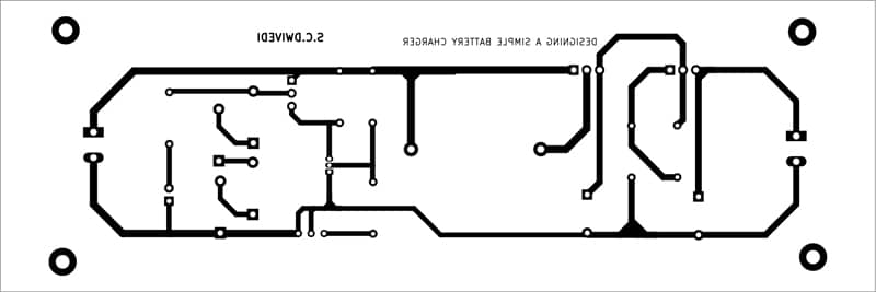
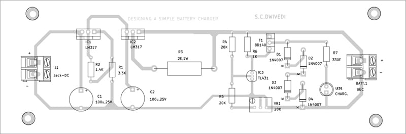
An actual-size, single-side PCB for the charger circuit is shown in Fig. 3 and its component layout in Fig. 4. After assembling the circuit on PCB, enclose it in a suitable box. Connect the input across J1 and the battery under charge (BUC) at BATT.1.
For setting the threshold voltage for the adjustable shunt regulator, in place of the cell connect a regulated power supply. Keep the output voltage the same as the threshold voltage you want to keep as cutoff voltage for the cell. Now, turn pot VR1 until LED1 starts glowing. This is the cutoff voltage at which the circuit will bypass the cell and current will start flowing through the series of diodes.
You can use the same circuit for charging different cell chemistries, such as lithium ion phosphate (LFP), lithium nickel manganese colbalt oxide (NMC), or even lithium-ion polymer (Li-Po) batteries, by setting the cutoff voltage for the adjustable shunt regulator TL431.
Charging more than one cell
To charge more than a single cell, which are connected in series, we need to replicate the charging and balancing circuit in series. The connections for a 3-cell charger are shown in Fig. 5.
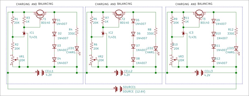
From Fig. 5 it is clear that the charging and balancing circuits are connected in series with each other and the whole series is connected in parallel to a power source. The cells that need to be charged are connected individually to a charging circuit each.
Since the cells may take different times to charge and discharge, the voltage of each cell in the battery pack may not be the same. Hence, when one of the cells is charged, the threshold voltage of TL431 in that specific circuit is reached and the cell in that circuit is bypassed, so the current flows through the four diodes in series and the indicator LED turns on.
Bonus. You can watch the video of the tutorial of this DIY project at https://www.electronicsforu.com/videos-slideshows/live-diy-constructing-li-ion-charger
Download PCB and Component Layout PDFs: click here
The author, Sharad Bhowmick, works as a Technology Journalist at EFY. He is passionate about power electronics and energy storage technologies. He wants to help achieve the goal of a carbon neutral world.