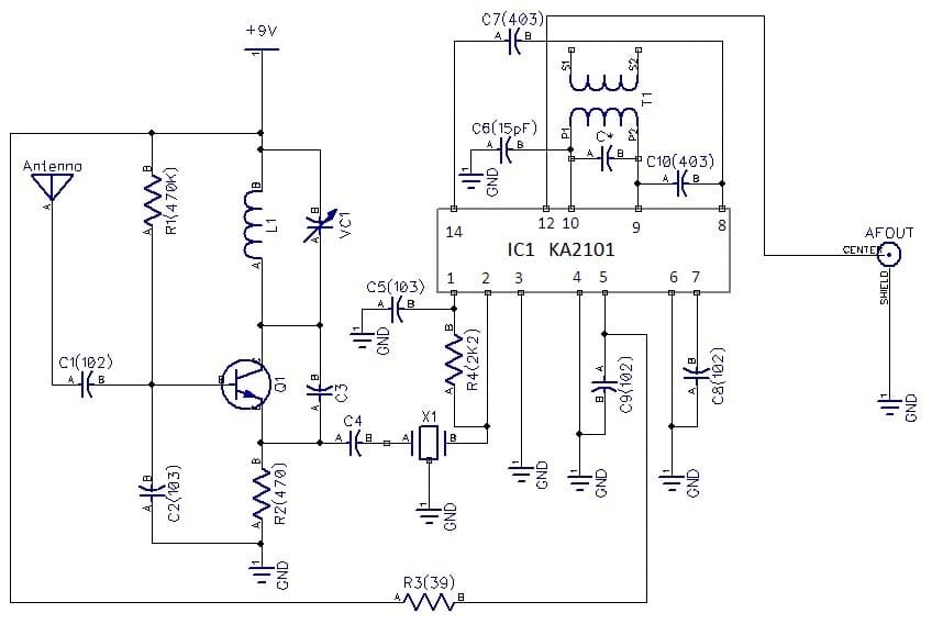
Here is a simple circuit diagram of 88-108 MHz FM Radio Receiver Circuit diagram. The circuit is very simple and the components used in this circuit can be easily available in a market and also the cost is cheap also.
This circuit works on a popular integrated circuit KA 2101.T1 works for RF Amplifier, Oscillator 93-113.5 MHz and mixer. And KA 2101 works for 5.5 MHz IF amplifier FM detector and AF preamplifier. A circuit diagram of AF amplifier is not given here but you can use TBA 810 (7 watt), e.t.c. The TBA 810 (7 watt) will performance good and quality sound output. You may also use 5.5 MHz ceramic filters in the state of 5.5 MHz IFT coils which will eliminate of tunning IFT coil and distortion.
Circuit Description
Transistor Q1 BF 494 is a high frequency transistor and will works here as RF amplifier, oscillator (5.5MHz higher than 88.00MHz-108MHz) and a mixer. A Coil L1 is a 23 SWG wire wound on 5mm air core with 5 turns. This coil and a 2-22pF trimmer will make an oscillation of frequency 5.5MHz higher than 88.00MHZ and 108.00MHz. A 5.5MHz output signal from emitter of Q1 is passed to a 5.5MHz IF input stage of IC1 KA2101 using a capacitor C4 (47pF).

Next is IC1 KA 2101 which is 14-pin IC. Pin 1 and pin2 is connected to a resistor R4. Pin 1 is also connected to ground through a capacitor C5 (0.04uF). A primary winding of T1 is connected to C* (68pF) in parallel and to a capacitor C6 (33pF).Pin 3 and 4 are grounded. Pin 5 is connected to +9 volts battery through a resistor 39 ohms. A capacitor C9 is .04uF which is connected to pin 5 of IC2 and ground. Pin 6 is also grounded. Pin 7 is also connected to ground through a capacitor C7 (.001uF). Pin8 and pin 14 are connected to each other through a capacitor C7.
Pin 9 and 10 are connected to a primary winding T1. A capacitor C* (68pF) is also connected to primary winding of T1. A capacitor C8 (102) is connected to ground and pin 7..

Pin 12 is an AF output pin. And an AF signal is connected to AF amplifier through connector 1.
Construction
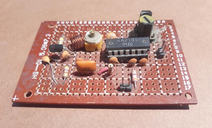
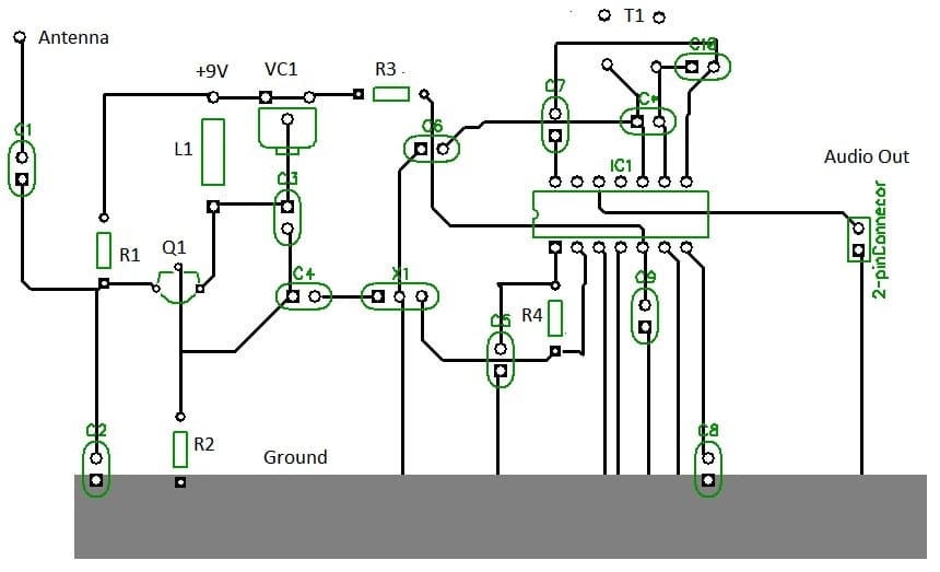
A suitable vero board of 5cm* 7-1/2cm can be use to build this project. Now we will need a 14-pin IC socket for IC1.
Now take a 14 pin IC socket and put on a middle of veroboard and solder it. Now place an IC1 KA2101 on IC socket.
Now take all the rest components and solder all by one by one as given on circuit diagram with 25 watt soldering iron. You’ll need also to solder a 9 volts battery clip to connect a 9Volts battery. 5.5 MHz IFT1 coils can be made by winding 23 turns of 37 SWG wire on 8mm ferrite core. C* (68pF) is to connect on a primary of 5.5MHz IFT coil.
Calibration and Adjustment
After placing all the components and soldering, next you have to do a calibration and adjustment.
Take 9 volts battery and connect it to a 9V battery clip. Take a small B&W TV receiver and turn it ON and select it on VHF range. Bring an antenna (75 cm long wire) near to a B&W TV and tune a tunning until you’ll see a plain on raster. As soon as you’ll see a plain raster on TV this will confirm you that RF amplifier, oscillator and mixer comprising transistor Q1 is working.
Next is to confirm if IC2 section is working or not. To do this Take AF Amplifier i.e. TBA 810, TBA 820 e.t.c. Now connect it to an output of AF amplifier of IC 2 KA 2101. You’ll hear a hissing sound from your AF amplifier. This will confirm that your FM radio receiver is working.
Next step is to tune 5.5MHz IF stage. Take a 5.5 MHz IF signal generator and connect its output to a capacitor C4 (47pF). Now take a plastic screw driver tune gently tune IFT coils T1. You should hear a tone sound from an amplifier. This will confirms that 5.5MHz using an IC1 KA 2101 section is working. Now disconnect 5.5MHz IF signal generator and reconnect C4 again. Next tune a VC1 2-22pF trimmer until you will hear a station clear and loud. You may also use an antenna 75cm if you receiving weak signal. Enjoy listening you radio.*
PARTS-LIST
Resistors (all 1/4watt)
R1: 470K
R2: 470
R3:39
R4: 2K2
Capacitors
C1:.001uF
C2: .04uF
C3:10pF
C4: 47pF
C5: .04uF
C6:.001uF
C7:.01uF
C8: 15pF
C9:.04uF
C10:403
Ceramic Filter
X1: 3-pin 5.5MHz ceramic filter
Semiconductor:
Q1: BF494
IC1: KA 2101
Miscellaneous:
9Volts battery, 9 volts battery clip, 14-pin IC sockets, vero board 5*7/1cm, 2-pin connector T1 (5.5 MHz IFT coil)
Author Prototype