


This is a simple FM radio using a popular TBA120S (14-pin). Most FM radio works on 10.7MHz IF frequency but this one does work on 5.5MHz IF frequency.
So, the components like the 5.5MHz ceramic filter, and 5.5MHz IFT coil used for this FM radio can be easily found in the market at a very low cost.
Also, an IC TBA120S used in this circuit can be easily found in the market at a very low cost or you can take off from your old Black & White TV receiver set etc.

| Category | Component | Specification |
|---|---|---|
| Semiconductors | Q1 | BF 494 |
| IC1 | TBA120S | |
| Resistors | R1 | 470K |
| R2 | 470 | |
| R3 | 2.2K | |
| R4 | 100 | |
| Capacitors | C1 | 0.001µF |
| C2 | 0.01µF | |
| C3 | 10pF | |
| C4 | 33pF | |
| C5 | 103 (0.01µF) | |
| C6 | 103 (0.01µF) | |
| C7 | 220pF | |
| C8 | 103 (0.01µF) | |
| C9 | 22µF/25V | |
| VC1 | 2-22pF trimmer capacitor | |
| Inductors | L2 | 5 turns of 23 SWG wire on 5mm air core |
| Miscellaneous | Ceramic Filter | 5.5 MHz, 2-pin |
| Veroboard | 5 x 7 cm | |
| IC Socket | 14-pin | |
| IFT Coil | 5.5 MHz | |
| Miscellaneous | Wires, soldering tools, etc. |
Circuit Working
The circuit is very simple. An IC1 TBA120S and Q1 (BF494) is the heart of this FM radio.
A few passive components and Inductor L1 trimmer capacitor VC1 (2-22pF), X1(10.7MHz ceramic filter) and T1 (5.5MHz IFT coil) were used in this circuit of FM radio.
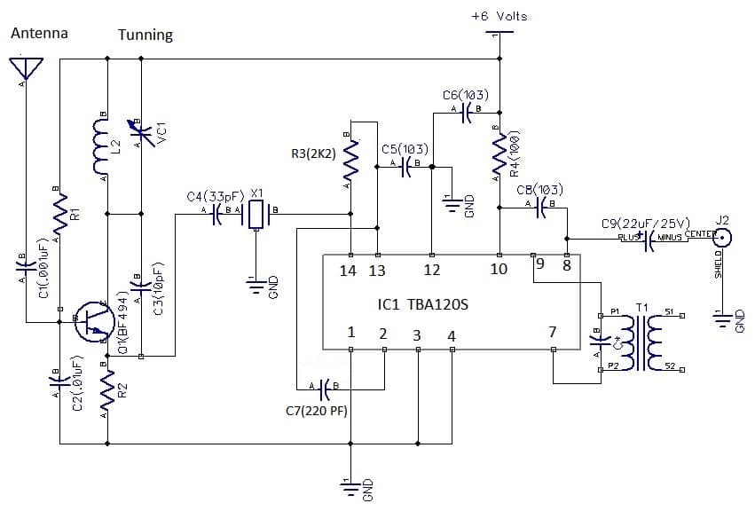
Resistor R1 (470K) is connected between a base pin of Q1 (BF 494) and +6Volts. Resistor R2 (470) is connected between the emitter pin of Q1 (BF494) and the ground.
Resistor R3 (680) is connected between pins 13 and 14 of IC1 (TBA120S). R4 (100) is connected to pin 11 of IC1 and to a +6V terminal.
Capacitor C1 (.001uF) is connected to an antenna (75cm long) and to baseQ1 (BF494).C2 (.01uF) is connected between a base of a Q1 (BF494) and to a ground. C3 (10pF) is connected between the emitter and collector of Q1 (BF494).
An output (pin 3) of X1 (5.5MHz ceramic filter) is connected to a pin 14 of IC1 (TBA120S). A 5.5MHz IF frequency is taken off from an emitter of Q1 (B494) and to a pin14 of IC1 (TBA120S) with a capacitor C4 (33pF). Pin no 2 of X1 is a connector to the ground.
Capacitor C5 (103) is connected between pin 13 and pin 12 and to a ground terminal. Capacitor C6 (103) is connected between +6V and ground. Capacitor C7 (103) is connected between pin2 and 13 of IC1.
C8 (103) is connected between pin 8 and pin 11 of IC1. A 5.5MHz IFT coil is connected between pin 7 and pin 9 of IC1. An AF output signal is taken out from pin 8 of IC1 (TBA120s) through an electrolytic capacitor C9 (22uF/25V). Pins 1,3 and 4 are connected to the ground terminal.
Construction and Testing
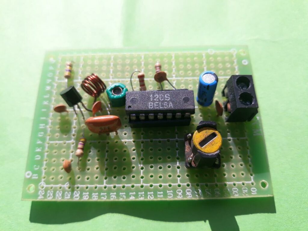
You’ll require a 5cm*7cm Vero board for making your TBA120S FM radio. You may use a PCB board as given in the article.
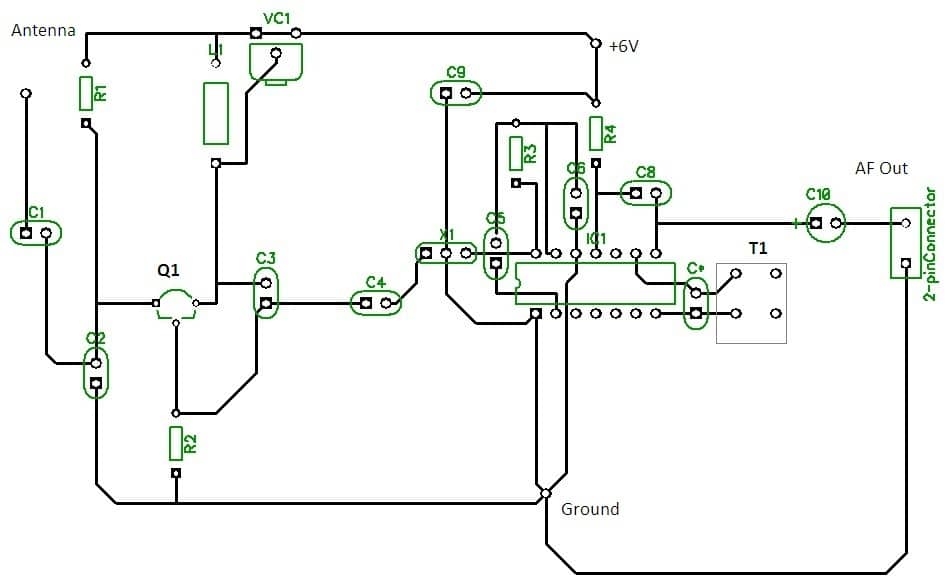
First of all take a 14-pin IC socket and put it on the middle of your vero board. Take a low-watt soldering iron and gently solder a 14-pin IC on the middle of a vero board.
Now insert an NPN transistor Q1 (BF494) on the left side of a vero board. Now insert all the remaining components like 5.5MHz IFT coil, resistors, capacitors or 5.5MHz ceramic filter and also solder all of them.
Next, we’ll test a finished FM radio. You’ll need a 5.5MHz signal generator. Connect a + 6V power to your FM radio and connect the AF output signal to an AF amplifier input.
Turn ON your 5.5 MHz signal generator and bring a 5.5MHz signal generator near your FM radio. You’ll hear an AF tone coming out from a speaker of an AF amplifier.
Next, connect a 75 cm wire to an antenna terminal. Slowly tune VC1 with a plastic screwdriver until you receive a signal. You may also tune your FM radio by squeezing coil L1 (5 turns of 23 SWG wire on a 5 mm air core).
Now you’ll hear a station from your FM radio. Finally, take a plastic screw and gently tune a 5.5MHz IFT coil until you’ll hear a clear sound from your FM radio. So, enjoy listening to FM radio.
Also Check Related FM Radio Projects
- Simple FM Radio Receiver Circuit
- Simple Stereo FM Radio Receiver Circuit
- FM Radio Receiver Using an IC TA7640AP
- FM Radio Receiver with TA2003
- Remote Controlled Stereo FM Radio
- FM Radio Using LA1260
- Simple FM Radio Using AN7236