
 Automated liquid filler machines are used to pack various liquid items such as oils, milk, and beverages in their bottling plants. But these machines are costly and not affordable by most small bottlers. This simple liquid dispenser releases a litre of the liquid each time the button is pressed.
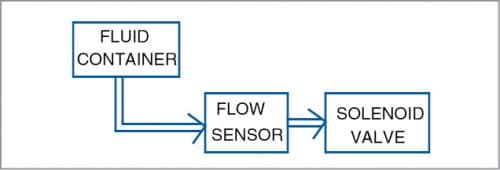
Block diagram of the dispenser shown in Fig. 1 illustrates its main stages.

Circuit and working
Circuit diagram of the simple liquid dispenser shown in Fig. 2 includes 5V, 7805 voltage regulator IC1, ATtiny85A AVR microcontroller (MCU) IC2, YF-S201 liquid flow sensor, commom-cathode bi-colour LED BICO1, normally-closed solenoid valve, and BD139 NPN transistor T1.
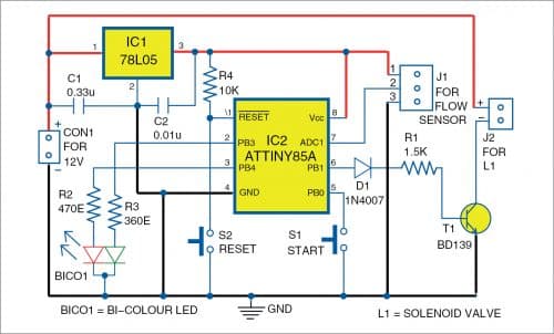
ATtiny85A AVR microcontroller is the brain of the circuit that controls the predefined quantity of the liquid flowing out. The flow sensor is connected to connector J1 and the solenoid valve is connected to connector J2.
In standby mode, the bi-colour LED emits red colour and the valve is de-energised. Every time button S1 is pressed, the valve gets energised and the liquid releases from the solenoid valve. The bi-colour LED blinks in green colour to indicate that the liquid filling is in process.
When liquid flow reaches the predefined quantity, the valve is de-energised by the MCU and now the bi-colour LED emits red colour to indicate that the filling process has been completed.
This cycle repeats whenever the button is pressed. Button S2 is used to manually reset the MCU.
Flow sensor
The flow sensor has a rotor along with a Hall effect sensor in the line of liquid passage. When liquid flows through the sensor, the rotor rotates. This causes the Hall effect sensor to output a pulse. Thus, the rate of flow (Q) can be measured as follows:
Rate of flow (Q) in litres/min= Output pulse frequency/7.5
But we want the quantity in litres and not the flow rate in litres per minute. By rearranging the above equation for litres, we get:
Number of litres=Number of output pulses/450
That means, it takes 450 pulses to flow one litre of liquid through the flow sensor.
Software code
The source code is developed using Arduino IDE. By default, Arduino IDE does not support ATtiny85 MCU. So, we need to add ATtiny board to Arduino IDE as follows:
Open FilePreferences and copy the below-mentioned link in the Additional Boards Manager URL: https://raw.githubusercontent.com/damellis/attiny/ide-1.6.x-boards-manager/package_damellis_attiny_index.json.
After this is done, open ToolsBoardBoard Manager. After opening Boards Manager, scroll down the list and find ‘attiny’ by Davis A. Mellis. Click on that and install it. After installing it, the ATtiny will be listed in the Boards menu.
Now, select ATtiny25/45/85 under Tools→Board. Then select ATtiny85 under
Tools→Processor and select 8MHz (internal) under Tools→Clock.
Next, make Arduino Uno an ISP programmer. For this, grab your Arduino Uno, connect it to your PC, and open Arduno IDE. Make sure you have selected the Arduino/Genuino Uno as your board, and open the ArduinoISP sketch from File→Examples option. Upload the ArduinoISP sketch to your Ardunio Uno. Your Arduino Uno is now an ISP programmer.
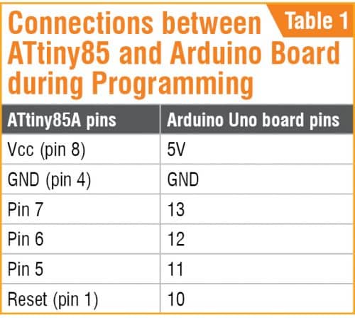
By default, the ATtiny85 runs at 1MHz. To make it to run at 8MHz, select ToolsBurn Bootloader option. Make sure that Arduino Uno board is programmed as ISP, and it is connected with the ATtiny85 through ISP pins as per Table 1. Upload the source code Simple_Liquid_Dispenser.ino by using the same Arduino board programmed as ISP.
Construction and testing
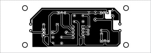
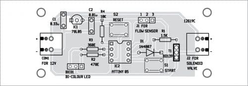
An actual-size PCB layout for the simple liquid dispenser is shown in Fig. 3 and its component layout in Fig. 4. After assembling the circuit on PCB, enclose it in a suitable plastic box. Install the flow sensor and solenoid valve according to your application.
Download PCB and Component layout PDFs: click here
Download Source Code
A. Samiuddhin, a circuit designer, is B.Tech in electrical and electronics engineering. His interests include LED lighting, power electronics, microcontrollers, and Arduino programming.