


 Presented here is a versatile battery charger circuit to charge batteries ranging from 6V through 48V. At home, garage or laboratory, you may have several rechargeable batteries with voltages rated at 6V, 12V, 24V, 36V, 48V or more. If so, you would need battery chargers for all of these with output currents of 0.5A to 1.5A, or more.
There is a large variety of battery chargers in the market. But linear chargers with mains power transformers are heavy, expensive and dissipate lot of heat. Chargers with pulsed technologies are relatively expensive and create a large spectrum of electromagnetic noise.

Circuit and working
Fig. 1 shows a simple low-cost and versatile battery charger circuit. The circuit is simple and lightweight, and does not generate any electromagnetic noise or heat. The only problem is that, it is not isolated from the mains power line.
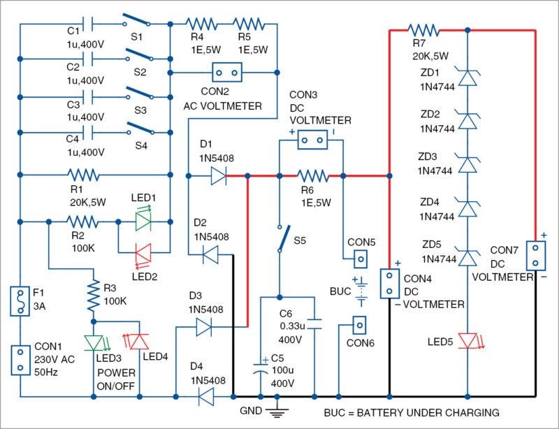
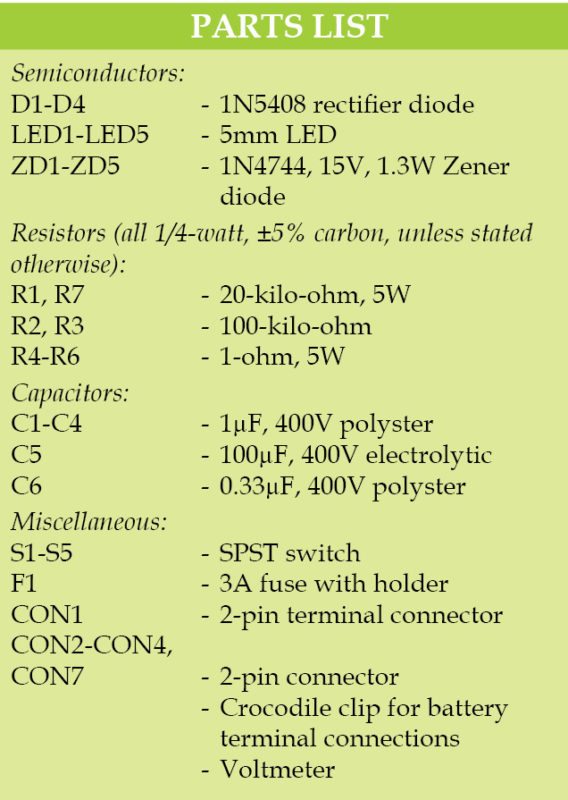
The circuit uses high-voltage capacitors C1 through C4. Values for these can be from 1µF to 22µF, with at least 400V rating. These are used to limit the charging current of the battery. Use of capacitors and switches is a flexible solution because it allows charging of batteries with voltage ratings of 6V to 48V, and even more.

Charging current is selected with switches S1 through S4. It can be controlled before the bridge rectifier comprising diodes D1 through D4, or after the bridge. For that purpose, voltmeters should be connected to connectors CON2 and/or CON3. Battery under charge (BUC) is connected between CON5 and CON6 using a two-wire cable with a crocodile clip.
The circuit can be used without a battery as an unregulated power supply. For that purpose, close switch S5. Capacitors C5 and C6 are used as filters for the power supply. Load can be connected in place of the battery across BUC terminals.
Voltage across BUC is measured using a DC voltmeter connected to CON4. Note that, without the battery across BUC, and if the battery has an internal open circuit, output voltage across CON4 can rise to around 300V.
Voltage across CON7 is restricted to 75V to 80V to protect the voltmeter. Zener diodes (ZD1 through ZD5) are rated at 15V, 1.3W. Zener diodes 1N4744, BZX85C15 or similar can be used. LED5 is on only if output is higher than 75V—this means the charger is working without load.
LED3 and LED4 are used as power on/off indicators.
Construction and testing
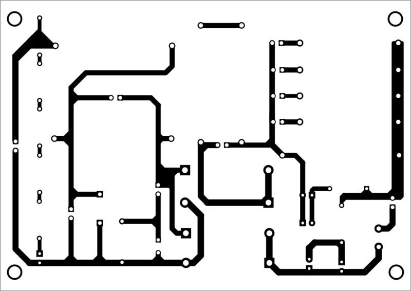
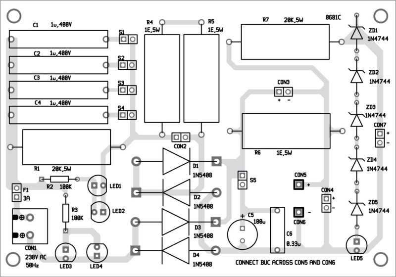
A single-side PCB layout for the simple low-cost, versatile battery charger is shown in Fig. 2 and its component layout in Fig. 3. After assembling the circuit on the PCB, enclose it in a suitable box.
The circuit is simple and, hence, does not need any adjustments after proper wiring has been done. The most important thing is to select C1 through C4 according to the targeted batteries. You can increase the resistors R4, R5 and R6 according to the needs.
The number of switches (S1 through S4) and associated capacitors (C1 through C4) can be increased or decreased according to specific needs, making the solution very flexible. Fix all switches and LEDs on the front side of the box.
Petre Tzv Petrov was a researcher and assistant professor in Technical University of Sofia (Bulgaria), and expert-lecturer in OFPPT(Casablance), Kingdom of Morocco. Now he is working as an electronics engineer in the private sector in Bulgaria

Where can I get the PCB and parts?
Nice Design. I will work for sure.
Thank you and best of luck.
i just need abstract of this project please.
Alts.
Kindly elaborate your query.
Very nice ,Am gonna have to try this
Fine circuit. I am sure to try this one. Can I get the PCB and components from “Kits N spares?
Why C1 through C4 are burned when 12 v battery connect in BUC
excelente pagina me ha ayudado mucho. muchas gracias a todos,,
De nada.
Any circuit for 120v mains?
1. Why some circuits like this don’t have filter capacitor at output for charging battery ?
2. How this charger can charge batteries of various voltages as the open circuit output voltage is same as input voltage ?
Is this a Constant current or constant voltage method charger ?