


 The fire alarm circuit presented here raises an alarm on detecting flames and high temperatures. It can be used in two ways: A single sensor board with an alarm board, or three sensor boards with an alarm board. The three separate sensor boards are to be installed at three different places, with the alarm unit installed at an appropriate location.
Circuit and working
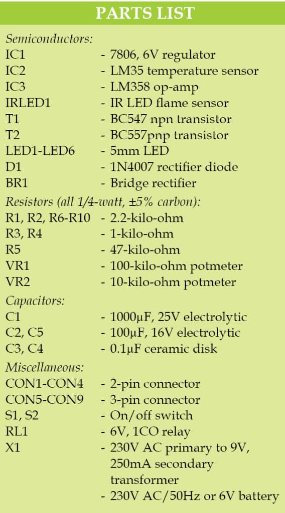
Circuit diagram of the fire alarm is shown in Fig. 1. It is built around a transformer (X1), 6V voltage regulator 7806 (IC1), temperature sensor LM35 (IC2), flame sensor IR LED (IRLED1), op-amp LM358 (IC3), transistors BC547 and BC557 (T1 and T2), a 6V single-changeover relay and a few other components.

The circuit senses ambient temperature using LM35 and checks the presence of flame with an IR sensor. Yellow- or red-coloured flames emit IR radiation, which is sensed by the IR sensor (IRLED1).

In case yellow/red flame, high temperature or both are detected, dual comparator LM358 triggers npn transistor T1. Transistor T1 conducts and its collector goes low to drive pnp transistor T2 into conduction. This, in turn, energises relay RL1 to activate the load (buzzer, lights and other equipment) connected at CON9.
One big advantage of this circuit is that in case the sensor board loses connection from the alarm board due to fire or explosion, transistor T2 gets activated due to logic low at its base and thus still energises the relay. So, place the alarm board at an appropriate remote location for monitoring.
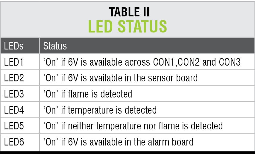
Normally, when there is no fire, LED3 and LED4 on the sensor board are ‘off.’ LED4 glows when the temperature crosses the set temperature range, while LED3 glows when the IR sensor detects IR radiation from the flame. LED5 glows during normal operation and goes off when it receives a signal from the sensor board.
The output of the sensor board at connector CON5 is marked as ‘A.’
Three similar sensor boards at different locations can be used by connecting their respective outputs to CON6 through CON8 of the alarm board. This arrangement is useful for monitoring multiple rooms, corridors, hotel rooms and staircases where alarm board can be placed at a safe and open area.
Initial setup for the fire alarm
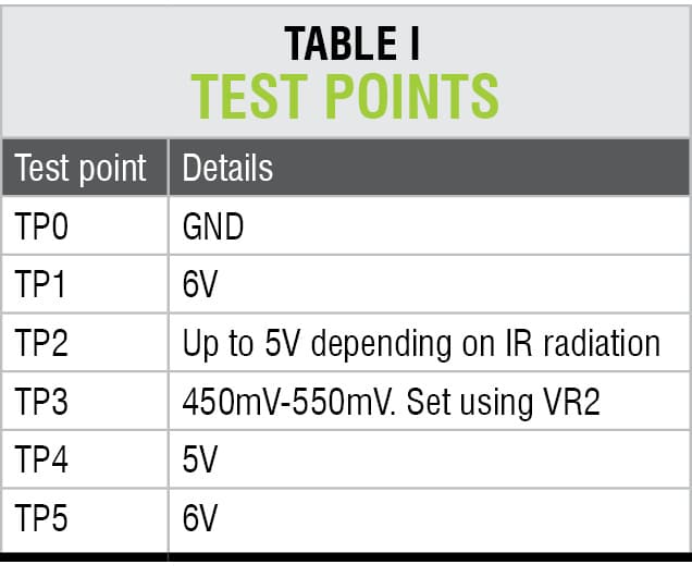
Once the sensor board (middle portion in Fig. 1) is ready and connected to 6V DC supply via switch S1, set VR2 to get around 450mV at TP3. (450mV means 45°C as set temperature, since LM35 outputs 10mV per 1°C temperature.) Now, using a hair dryer or some other small heat source, blow hot air on LM35. Once the temperature of LM35 crosses 45°C, LED4 glows. Stop the heat source. At pin 2 of IC3, you can set 450mV to 550mV for trigger temperature of 45°C to 55°C or any other temperature according to your requirement.
Next, light a candle and keep it about one metre away from IR LED1 sensor (flame sensor). Set VR1 such that LED3 goes off and glows again if the candle is moved little closer to the IR sensor.
Connect power supplies to sensor boards and the alarm board. Switch on S1 and S2. Test the relay operation by increasing the temperature and also by bringing the candle flame nearer to the IR sensor.
Construction and testing
An actual-size PCB layout of the fire alarm including power supply, sensor board and alarm board is shown in Fig. 2 and its components layout in Fig. 3. Cut the PCB along the dotted lines. Assemble the power supply, sensor board and alarm board separately. Enclose these in a suitable box. Connect the respective connectors between the power supply, sensor board and alarm board.


Download PCB an Component layout PDFs: click here
The circuit works off 230V AC, 50Hz. Alternatively, you can use a 6V battery. In this case, do not assemble power supply PCB and connect 6V battery directly at CON4.
After assembling the circuit, verify voltages as shown in Table I. Also refer Table II for the status of each LED in the circuit. Fix LEDs on the front panel and label their functions.
 When you are using a single sensor board, connect CON1 to CON4 for power supply and CON5 to CON6 for signal sensing. In this case, CON2, CON3, CON7 and CON8 are unused.
For the arrangement using three sensor boards, you can assemble the sensor boards separately using the same sensor circuit and power supply taken from CON1, CON2 and CON3 respectively.
For reading more Electronics Projects: click here
