


 This is a simple tester with square-wave oscillator for single and dual operational amplifiers (op-amps). These op-amps are widely used in different projects. You can use and reuse these, but an op-amp is often required to be tested before use in new and different projects.
There are many single op-amps available under different names such as NE5534, TL071 and LM741, each having significant differences in slew rate, output drive capabilities and other parameters. You need to compare these parameters to select the most appropriate one for your application. Here is a simple op-amp tester circuit designed to solve these problems.
Circuit and working
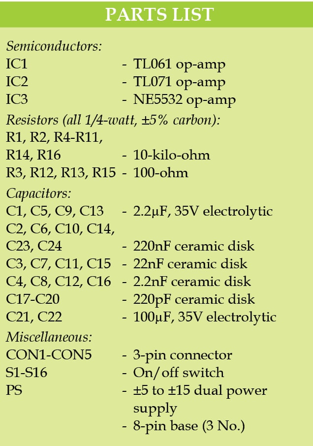
The circuit diagram of the simple tester for Operational Amplifiers is shown in Fig. 1. It is built around single op-amps TL061 (IC1) and TL071 (IC2), a dual op-amp NE5532 (IC3), sixteen on/off switches (S1 through S16) and a few other components.

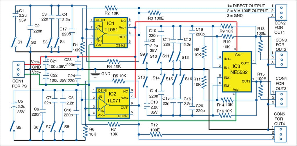
The circuit can be used to test two single op-amps (IC1 and IC2) and one dual op-amp (IC3) very conveniently. Sometimes, it can be difficult to decide whether to use two single op-amps or one dual op-amp in a project. You need to compare parameters of the two single op-amps with those of dual op-amp in that case. IC1 and IC2, and IC3 can be of the same type, such as NE5534 and NE5532, respectively.
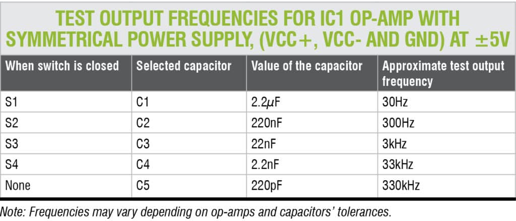
The circuit produces five test output frequencies on selecting switches S1 through S4. Test output frequencies for IC1 are given in the table on the next page. Use S5 through S8 for testing IC2, and S9 through S16 for testing IC3. For IC2 and IC3, you can have the same test frequencies.

IC3 can be tested at the same or different frequencies. Since IC3 is a dual-op-amp, there can be cases where one of the inbuilt op-amps of IC3 is operational while the other op-amp is damaged, and vice-versa. (Note that, if damaged, you will not get output frequencies as listed in the table.)
The circuit operates with a bipolar power supply, but IC1, IC2 and IC3 have the same power supply lines. Power supply can be symmetrical or non-symmetrical, and this will change the parameters of output signals. The circuit operates in full power supply range of the op-amps. Maximum power supply is limited by op-amps, maximum voltage rating of capacitors used in the tester circuit and driving capabilities of op-amps.
Output frequency of the tests can be changed easily and to a large scale according to needs. Driving capability of the op-amps can be tested with external loads. For that, each op-amp under test has a direct output line as well as output with series resistor of 100 ohms. Op-amps will be unstable if you test them directly with capacitive and inductive loads, so 100-ohm resistors are provided at output.
The circuit does not need any adjustment to operate properly. It can be used to test many op-amps, including low-speed op-amps such as LM741 and MC1458, and faster op-amps such as OPA132 and OPA134.
Construction and testing
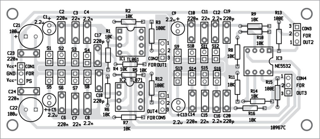
An actual-size PCB layout of the simple tester for single and dual op-amps is shown in Fig. 2 and its components layout in Fig. 3. Assemble the circuit on the designed PCB. Connect a suitable ±power supply (PS) across CON1. Connect all switches (S1 through S16) on the front of the cabinet to select a particular frequency, as shown in the table.
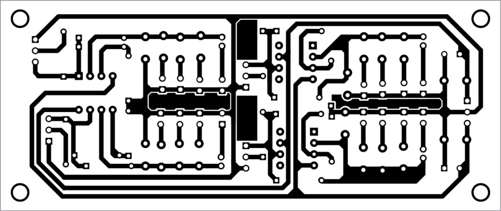
Download PCB and component layout PDFs: click here
It is recommended to use IC bases for IC1, IC2 and IC3, so that you can insert and remove them easily.


Very nice. Built one and it does exactly what I want, qualifying OP AMPS for audio projects. Thanks
You are most welcome.