


 Smartphone batteries need to be charged frequently, generally more than once a day. But their charging cables tend to get damaged after some time due to excessive use, which can be annoying—especially if they fail when these are needed the most. A wireless charger can be a convenient alternative; you simply set it up and forget it. But how does it work, exactly?
While wireless charging may seem like a recent invention, its origin dates to more than a hundred years. The credit for it goes to the famous Serbian-American inventor, Nikola Tesla.

Working principle
In the late 1800s, Nikola Tesla successfully transmitted electricity through the air. He used a process called resonant-inductive coupling for it, which works by creating a magnetic field between a transmitter (to send electricity) and a receiver (to receive the electricity) to power light bulbs in his New York City laboratory.
A few years later, he patented the Tesla coil—a tower with a coil at the top that shot bolts of electricity. Tesla had much grander vision of a wireless power grid, but his dreams were never realised. Now the same basic principle of inductive charging can be used for a smartphone’s charging wirelessly.
| Bill Of Material | ||
| Component | Quantity | Purpose |
| 0.3 – 0.4mm dia enamelled copper wire | 5 metres | For transmitter and receiver coils |
| Resistor 1k | 1 | For current limiting |
| Transistor BC547 | 1 | For switching |
| LED | 1 | For half-wave rectifier |
| USB cable | 1 | For charging mobile |
| 9V battery with connector | 1 | For transmitter power supply |
Construction
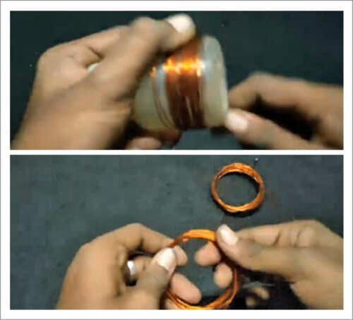
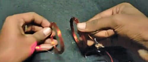
You may use a plastic bottle having about 8cm dia, like the author, for winding a coil over it. Or you can use a PVC pipe or any other cylindrical object to wind the coil. Wind 15 turns of the enamelled copper wire, terminate, and wind another 15 turns, like a centre-tapped transformer. Similarly, wind 15 turns of the enamelled copper wire to make the receiving coil.
The author used BC547 NPN transistor for oscillator in his circuit, but instead TTC5200 transistor may be used for better results.
Connect 1k resistor to the transistor’s base to limit the current. Connect the centre-tapped coil to positive terminal of the battery whose negative terminal should be connected to the transistor’s emitter. The other two ends of the transmitter coil should be connected to transistor’s collector and base terminals, as shown in Fig. 3, through the 1k current-limiting resistor.

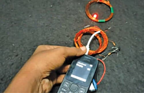
The receiving coil’s ends are connected to the USB cable through LED, which is used here for indication and as a half-wave rectifier.
Principle of operation
The transmitter coil connected to battery through the transistor makes the oscillating circuit. The oscillating current inside the transmitting coil causes it to emit 1MHz magnetic field. This oscillating magnetic field induces an electrical current in the receiver coil.
The induced current is an alternating current, so it needs to be converted into DC for mobile charging. The LED used in the circuit rectifies the current into DC besides its use as an indicator.
Sakthivignesh R. is Engineer – SCADA system
A mobile phone requires a precise 5v source capable of providing a minimum of 300 mA for charging the 3.7v Li-ion battery inside. This project has no way of regulating the output at 5v.
Don’t believe it has been tested properly.