 Here is a simple single-channel audio amplifier that can be made using IC LM380N. As per the datasheet, LM380N delivers an output of 2.5 watts with an 18V power supply and an 8-ohm speaker. This project was tested using a 12V DC power supply.
The power supply can be 230V to 12V DC adaptor or a 12V battery. But a 12V battery would be better as an AC/DC adaptor may cause humming noise. The LM380N is an inexpensive 14-pin PDIP IC that is easily available in the market.
Circuit and working
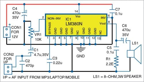
Circuit diagram of the audio amplifier is shown in Fig. 1. A suitable pot (VR1) is connected at input pin 2 of the IC. An 8-ohm, 3-watt speaker is connected to IC’s pin 8 through 470µF electrolytic capacitor C6. IC’s pin 14 is connected to positive terminal of 12V supply.

Audio input is given to pin 2 of IC1 through 4.7µF electrolytic capacitor C1 and pot VR1 that is used for volume control. Pins 3 through 7 and pins 10 through 12 of IC1 are all connected to ground. Pins 9 and 13 are not connected.
Construction and testing
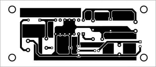
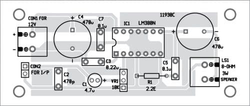
A PCB layout for the amplifier is shown in Fig. 2 and its component layout in Fig. 3. A suitable Veroboard can be used in place of the PCB.


Place a 14-pin IC socket in the middle of the Veroboard. Then place all other components on the Veroboard and solder them as per circuit diagram. Keep connector CON1 on left and speaker LS1 on right side of the Veroboard. Fix pot VR1 somewhere in the middle of the Veroboard.
Connect all the GND pins of IC1 to ground. You may also use a suitable heat-sink for these ground pins.
To test, after mounting the IC on its socket, connect the 8-ohm, 3-watt speaker to the right side connector LS1. Connect a 12V battery or 12V AC/DC adaptor to positive and negative supply terminals of CON1.

Keep the volume control (VR1) wiper in its middle position and touch the audio input terminal with a metal screwdriver. If you hear humming sound from the speaker, it means the amplifier is working.
Connect audio from your mobile or laptop to input CON2 of the amplifier. Adjust pot VR1 until you hear a pleasant and clear sound.
Raj K. Gorkhali is an electronics hobbyist and a regular contributor to EFY


How potentiometer value should be chosen for any amplifier ?
Is it according to input impedance or according to source signal strength ?
I’ll try this and revert for comment