


IoT-based smart home automation system lets homeowners control appliances conveniently from their smartphones and laptops. Appliances and lights frequently stay on unnecessarily, resulting in significant energy wastage.
Implementing home automation and smart technology can automate energy-saving routines, such as turning off lights or shutting down electronics when not in use. Smart home automation enables homeowners to monitor their appliances even when they are away.
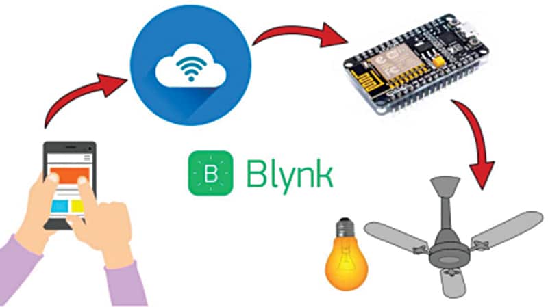
Smart home technology can enhance overall quality of life by simplifying daily tasks and reducing stress. For example, automated lighting and blinds can create a more comfortable and pleasant living environment. The purpose of this system is illustrated in the block diagram shown in Fig. 1. Components used in the automation system are listed in the bill of materials Table 1.

| Table 1: Bill of materials | ||
| Component Name | Quantity | Description |
| ESP8266 (MOD1) | 1 | For programming |
| Relay Module 4 Channel (MOD2) | 1 | Male-to-female jumper wires |
| Male to female jumper wires | 10 | For connection |
| 5V battery/power bank | 1 | Power supply |
Smart Home Automation System – Circuit Diagram
The circuit of the smart home automation system is shown in Fig. 2. It is built around ESP8266 (MOD1), a four-channel relay module (MOD2), and a few jumper wires. A 5V battery/power bank is used to power the system. Connections between ESP8266 and relay inputs are given in Table 2, while connections between the relay module and load (bulb or fan) are given in Table 3.

