


The smart lock uses a smartphone app for unlocking, which is suitable for bicycles and motorcycles, with enhanced security features and battery status monitoring through the app.
Smart locks represent a significant advancement in locking technology, moving beyond the traditional key and lock hole system. These innovative devices allow users to unlock them using a smartphone app, eliminating the need for physical keys. They are versatile and can be used on various items, such as bicycles and motorcycles. For enhanced security, smart locks require the correct password for unlocking. Users can conveniently monitor the status of their smart lock, including its battery power, through the associated smartphone app. Renesas has launched a smart lock reference design to simplify the design process.
The smart lock, powered by three AAA batteries and the RL78/G1D BLE MCU for efficient operation, utilizes a DC motor-controlled latch for locking and unlocking. Its security is enhanced by a motor current detection circuit that signals the lock’s status and an integrated alarm that activates if the lock is tampered with, such as cutting the lock core. This alarm can be deactivated via a smartphone app, which also offers password management and the ability to monitor the lock’s status, including battery life and lock condition. Designed for various uses, including bicycles and motorcycles, the smart lock ensures safety by requiring the correct password for access, with user passwords securely stored in its internal data.

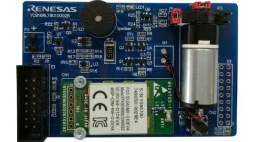
The board of the smart lock is built around the RL78/G1D (R5F11AGJ) as its main MCU, featuring 256 KB of Flash ROM and 20 KB of RAM. It is powered by three AAA batteries, with a stable 3.3V power supply achieved through the XC6206 chip. The battery voltage is monitored via an A/D port. The smart lock uses a DC motor to move the latch, enabling lock and unlock functions. The latch’s position is detected through a motor current detection circuit. When the motor reaches a preset position, the lock engages, causing an increase in current. This change in current is then amplified and compared, resulting in a jump edge signal. This signal is detected by the external interrupt INTP5, allowing for accurate determination of the latch’s position and the subsequent stopping of the motor.
A jumper simulates the chain in the smart lock, and a transistor driver circuit monitors its connection status. If the jumper, representing the chain, is severed while the lock is engaged, the INTP3 is triggered, activating an anti-theft buzzer. This buzzer, powered by a transistor, is a security feature. To deactivate the alarm once triggered, users can connect the smart lock to a smartphone app, allowing for efficient management and control of the lock’s security functions.
Renesas have tested this reference design. It comes with a Bill of Materials (BOM), schematics, Gerber file, Printed circuit board (PCB) layout, etc. You can find additional data about the reference design on the company’s website. To read more about this reference design, click here.