


This project implements a Smart Plug project which can measure the Power, Current, Voltage of any load connected to it. The Android phone interface can be used to read the values from the plug and also controls its ON/OFF. The values are also regularly sent to the Android device for monitoring.
This project will use an Renesas GR Peach as the main processor to measure the AC current and voltage of the load using the ACS 712 Current Sensor, a voltage divider and send the data from a HC-06 Bluetooth device to an Android phone. This circuit also has a relay controlled by the GR Peach to turn-off and turn -on the load using the Android device. The Android phone runs an App developed on App Inventor and will display the voltage, current, power and Wh. The App also has a graphing feature which will display the voltage and current as a bar chart in real time.
This project will outline the method to write and build the GR Peach program, and also writing the Android Application using the cloud application called App Inventor.

Block Diagram of the system
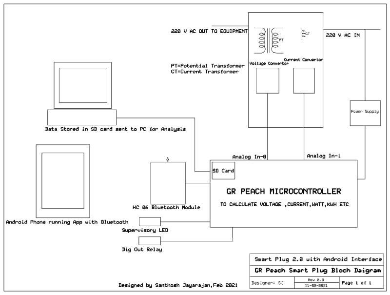
The system consists of the following parts:
- The ACS 712 Sensor (Current Sensor) that will read the AC Current and generate an analog signal proportional to the AC Current. (1-5000 ma ,185 mv/A AC)
- A 230V to 5 V rectified circuit (Transformer and rectifier) to read the AC voltage which is used to calculate power and Wh. A voltage divider is used to reduce the voltage to the GR Peach range.
- The GR Peach board which is the heart of the system and reads the voltage and current from the field and converts it into power and Wh(Watt Hour) and send it serially using the Bluetooth module HC -06.
The GR Peach is a very powerful development board which has built-in Ethernet and SD Card capabilities. With the new GR – IDE it is as easy to program as the Arduino. - A Relay module which is controlled by Bluetooth command from the Android device. This relay is used to turn the appliance on and off.
- The HC-06 is a Bluetooth trans- receiver that will accept signals from the GR Peach and send data to a paired Bluetooth device in this case the smart-phone.
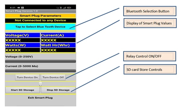
- The Android device is a smart phone that runs the App to display the Smart Plug parameters provide graphing features as well.
- The circuit also has a supervisory LED to indicate if the program is running properly.
This project can be explained as follows:

- The circuit diagram for connection of the ACS 712 Current sensor, Voltage Rectifier Circuit to the GR Peach.
- The Arduino program that reads the Current sensor, voltage signals convert it to the scaled range and sends the converted signal via Bluetooth to the Smart phone.
- Development of the Android App that reads the Bluetooth signal and displays it with bar graphs and labels. (Development is done using App Inventor that is a cloud application to develop smart phone Apps.)
GR Peach Smart Plug Circuit Diagram

Component List:
-
Sl.No Component Quantity 1. Renesas GR Peach Controller Board. 1 2. HC-06 Bluetooth Module 1 3. ACS 712 Current Sensor (0-5 A) 1 4. 0.5 K ¼ Watt Resistor 1 5. 5 V Relay – 3.3 Volts Pick-up 1 6. 1N 4001 Diode-Free-Wheeling 1 7. Power Supply for GR Peach 1
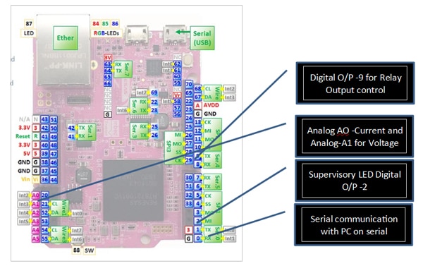
The GR- PEACH Image is given below with the Pin usage
The GR Peach Smart Plug Circuit
The circuit for the GR Peach Smart Plug consists of the following Sub Systems:
- The GR Peach is the heart of the circuit and interfaces all the field sensors and does the mathematical calculations to calculate power and Wh.
- A supervisory LED is connected to Pin -2 as an indication that the circuit is working properly. If the circuit goes into a non-recoverable infinite loop the LED will not blink.
- A 5 V relay with a pick-up voltage of 3.3 V is connected to Pin 9 to control the power to the controlled device. This relay can be turned off and on by using the Android device.
- The system voltage is measured by using a 230 V/0-5 V transformer with a bridge rectifier and voltage divided to get 3.3 V for 250 V. The calculation of the voltage is done by the GR Peach. The Analog Input A1 is used for this input.
- The system current is measured by an ACS 712 AC Current sensor which will output a voltage proportional to the current using the Hall Effect. The microcontroller will do a 1 second sampling and find the maximum and minimum voltage and calculate the RMS current. This Analog input is connected to A0.
- Bluetooth functionality is achieved by a HC-06 Bluetooth Trans-receiver which requires a 5 V supply but has signal level of 3.3 V and thus can be connected directly with the GR Peach at Serial0 with TX on Pin 1 and RX on Pin 0.
Note: Since the GR peach is essentially a 3.3 V device all signal including Analog Input have to be at this level. For this reason, there are voltage dividers provided for the voltage and current signals.
The GR Peach Program in GR-IDE
The GR Peach program is given below. The GR Peach program can be entered using the GR -IDE and compiled before transmitting to the board using a USB cable.
The various versions of the GR -IDE can be downloaded from this link
After entering the program and compiling the compiled program can be downloaded into the GR -PEACH.
After downloading the ZIP file from the link above the file can be unzipped and the program can be run by double clicking on the ide4gr.exe file in the main folder.
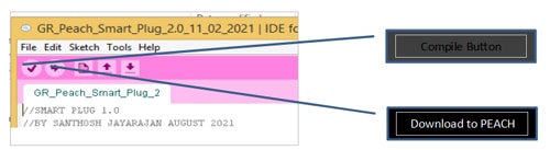
The controls for the compile and download are shown in the figure below:
The GR Peach program developed using GR IDE
//SMART PLUG 2.0
//BY SANTHOSH JAYARAJAN FEBRUARY 2021
//USED:
//1. 712 SENSOR FOR CURRENT MEASUREMENT
//2. HC-06 MODULE FOR BLUETOOTH COMMUNICATION
//3. 5 V TRANSFORMER FOR VOLTAGE MEASUREMENT
//4. GR PEACH AS THE PROCESSOR
// NOTES:COMPILED – OKAY
///
//
#include<Arduino.h>
#include <SD.h>
const int Current = A0;
const int Voltage = A1;
const int RELAY1 = 9;
const int SUPLED = 3;
//START TIMER FOR CURRENT CALCULATION
Timer volt_timer;
File file;
//START A TICK TIMER FOR LED BLINK, BT Send, WH Counter
Ticker LEDTimer;
Ticker BTTimer;
Ticker WHCount;
//VARIABLE DEFINITION
long CurrRaw;
long CurrCalc;
int c_begin;
int c_end;
int Curr_Max;
int Curr_Min;
int VoltRaw[100];
long VoltScratch_1;
long VoltCalcRaw;
float VoltCalc;
float Volt_m_factor;
float Volt_zero_factor;
//FOR WH COUNTER
float Wh;
//VARAIABLES FOR VOLTAGE CALCULATIONS
float Power;
int BTin;
//SETUP SUBROUTINE
void setup()
{
//FOR SERIAL0 The Pins used are TX=1,RX=0
Serial0.begin(9600);
Serial.begin(9600);
}
//SUBROUTINE DEFINITION FOR ENERGY
void WHCounter()
{
Wh=Wh+Power/360;
}
//READ THE ANALOG CHANNELS
void ReadAnalog()
{
//CALCULATE THE VOLTAGE
Volt_m_factor=1.0;
Volt_zero_factor=0.0;
VoltScratch_1=0;
for(int n=0;n<=10;n++)
{
VoltRaw[n]=analogRead(Voltage);
wait_ms(100);
VoltScratch_1=VoltScratch_1+VoltRaw[n];
}
VoltCalcRaw=VoltScratch_1/10;
//0-1.0 FOR 0-250 V AC volts
//Y=MX+C
VoltCalc=VoltCalcRaw*Volt_m_factor+Volt_zero_factor;
//CALCULATE CURRENT
Curr_Max=0;
Curr_Min=1000;
c_begin=volt_timer.read_ms();
while(volt_timer.read_ms()-c_begin<1000)
{
CurrRaw=analogRead(Current);
if(CurrRaw>Curr_Max)
{
Curr_Max=CurrRaw;
}
if(CurrRaw<Curr_Min)
{
Curr_Min=CurrRaw;
}
CurrCalc=(Curr_Max-Curr_Min)*3.3/676;
}
}
//TURN ON RELAY OUTPUT-1
void Relay_1_on()
{
digitalWrite(RELAY1,1);
}
//TURN OFF RELAY OUTPUT-2
void Relay_1_off()
{
digitalWrite(RELAY1,0);
}
//CALCULATE THE POWER PARAMETERS
void CalculatePower()
{
//CALCULATE POWER
Power=VoltCalc*CurrCalc;
}
//CHECK FOR BT SERIAL DATA
void CheckBTData()
{
if(Serial0)
{
BTin=Serial0.read();
if(BTin == 1)
{
Relay_1_on();
}
if(BTin == 2)
{
Relay_1_off();
}
if(BTin == 3)
{
if(!SD.begin())
{
Serial.println(“Card failed, or not present.”);
}
if(SD.begin())
{
Serial.println(“Card OK Saving Data.”);
File file = SD.open(“sample.txt”, FILE_WRITE);
if(file)
{
file.print(“Current:”);
file.print(Current);
file.print(“Voltage:”);
file.print(Voltage);
file.print(“Power:”);
file.print(Power);
file.println( “\”\r” );
}
}
}
if(BTin==4)
{
file.close();
Serial.print(“File Closed..”);
}
}
}
//TOGGLE THE SUPERVISORY LED
void ToggleSupLED()
{
if (digitalRead(SUPLED)==1)
{
digitalWrite(SUPLED,0);
}
else
{
digitalWrite(SUPLED,0);
}
//SUPERVISORY LED-2
if (digitalRead(LED1==1))
{
digitalWrite(LED1,0);
}
else
{
digitalWrite(LED1,1);
}
}
//SEND POWER PARAMETERS TO BT DEVICE
void SendBT()
{
Serial0.print(VoltCalc);
Serial0.print(“,”);
Serial0.print(CurrCalc);
Serial0.print(“,”);
Serial0.print(Power);
Serial0.print(“,”);
Serial0.print(Wh);
//SEND DATA TO PC FOR DEBUGGING
Serial.print(VoltCalc);
Serial.print(“,”);
Serial.print(CurrCalc);
Serial.print(“,”);
Serial.print(Power);
Serial.print(“,”);
Serial.print(Wh);
}
//MAIN SUBROUTINE
void loop() {
//TIMER TICKER ASSIGNMENT FOR TIME CONTROLLED SUB ROUTINES
LEDTimer.attach(&ToggleSupLED,1.0);
BTTimer.attach(&SendBT,5.0);
WHCount.attach(&WHCounter,10.0);
while(1)
{
ReadAnalog();
CheckBTData();
CalculatePower();
}
}
Flow Diagram of GR Peach Program
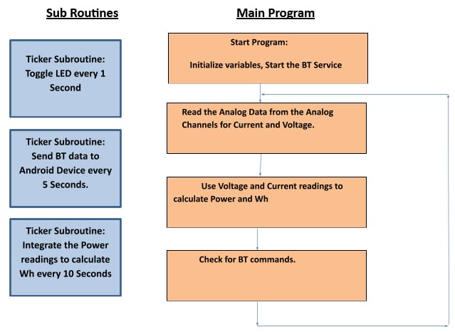
The GR Peach program can be sub divided into two parts:
- The main Loop Program
- The Timer Ticker program that run at regular intervals.
In the main loop() program we initialize the sub-routine tickers and then continuously run the Analog Read, Power calculation and check for BT command sub-routines. The Current and voltage are measured by the Analog Inputs and calculation of power is done. The main loop also checks continuously for any Bluetooth commands from the Android device.
In the Timer subroutines the various time sensitive sub routines are run. In the main loop() subroutine the timer routines are initiated by commands below:
LEDTimer.attach(&ToggleSupLED,1.0);
BTTimer.attach(&SendBT,5.0);
WHCount.attach(&WHCounter,10.0);
The LED Timer is set to run every 1 second to blink the supervisory LED which indicates the correct operation of the program.
The SendBT() sub routine sends the Data of the Smart Plug every 5 seconds. The data sent is voltage, current power and Wh.
The final sub routine is WHCounter() which runs every 10 seconds to do the integration of the power for Wh(WattHour) calculation.
The App Inventor Program
The MIT (Massachusetts Institute of Technology) team have produced a Cloud based program that can be used to develop apps for Android Phones or devices. The program can be accessed by anyone with a Google account.
The URL for the program is: http://ai2.appinventor.mit.edu/
The application uses very easy to build control blocks that can be “latched” together to build the program. This program usage is very similar to Scratch.
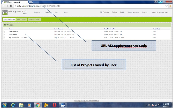
The opening screen of the program looks like the screen shot below. The opening screen opens with the list of projects that have been saved.
The required project can be opened by double clicking on the required project.
The programming is done in two views:
- The Designer view where the various components are placed on the palette. This will represent how the components look on the device.
- The Block view is where the programming is done. The various programming blocks are interconnected using various programming functions that will snap together like a jig-saw puzzle.
To explain the basics of working of the program the explanation of the various sub blocks are as given below:
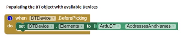
Starting the Bluetooth Device:
Here the block displays all the available Bluetooth Devices and display the address and names. This block is executed before selecting any Bluetooth device. The device in this program will appear as HC-06 with a hexadecimal address. This part of the program is needed to connect the Android device to the HC-06.
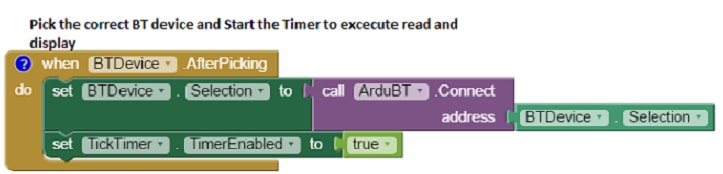
 Selecting the Bluetooth Devices.
Here the Bluetooth device that is selected is connected to the mobile device. This block also enables the “Tick Timer” which periodically updates the display and graph.
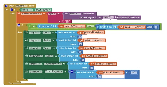
 Main Timer Block
This is the main timer block which reads the data from the Bluetooth device and then displays the values on the screen and also draws the bar graph. After voltage and current values are plotted on a bar chart using the slider control. The updating takes place in real time. This block checks the data which is sent by the GR PEACH and separates the data at the commas and loads the values into the various text boxes. The Voltage and the Current are also displayed as a bra graph using the slider control.
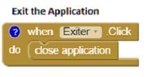
 Exit the application
This block is used to quit the application.
 Variables used in the application
These are the variables declaration and initialization. In this case the variable is a Global variable called BTReceive.
In the APP Inventor when the Project is Built a QR code is generated which can be scanned for immediate installation on the phone. The APK file can also been generated for storage on the phone and installation.
![]() A APK version of the program is available to directly load to the Android device.
A APK version of the program is available to directly load to the Android device.
Conclusion
This project introduced a simple way to use the GR Peach board and a cheap Bluetooth module the HC-06 to send data to an Android device and display the data and plot the graph.
The basic idea behind this program is to use the many capabilities of the Mobile devices like Color display, Bluetooth, Wi-Fi etc. to act as an interface to collect data from external devices and manipulate them. In this case the external device is the GR Peach and the Android Device running the Application manipulates and displays the data.
This project also introduced the use of App Inventor to write simple programs for Android devices using blocks.
