


 Detecting the velocity of vehicles and objects is often needed for research and data collection purposes or for setting speed limits on roads and highways to avoid accidents. For such tasks, a reliable solution that wirelessly measures the speed of a fast-moving object can be developed, which uses the Doppler effect. It relates to the change in a wave’s frequency and wavelength caused by the varying distance between the wave generation/transmission from an object (source) and reception/sensing of that wave (watcher or observer).
So in today’s project, you will learn to create a Doppler effect-based smart radar system for measuring velocity with the help of the transmission and reception of microwave signals.
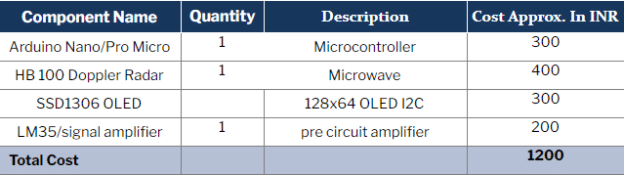
Bill of Materials

DIY Smart Radar System – Code
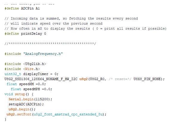
First, install the Analog Frequency library for measuring the frequency pulse and detecting the signal waves (this will later convert into the object speed). Then, install the U8g2 library for the interfacing of the OLED display module to display text icons.
After installing the frequency library, include it in the code and then define the pin numbers for the radar sensor. Now in the setup function, add the code for the serial port having a baud rate of 9600.

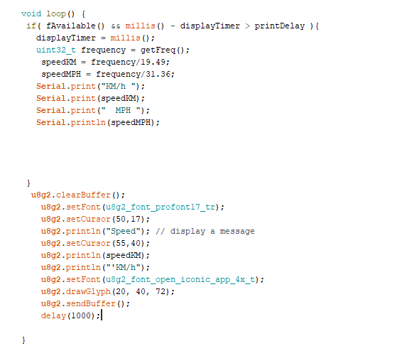
Next, create a loop, which will update the wave frequency according to the Doppler effect, convert it into the speed of the moving object and send its value to the serial port. The frequency to speed conversion is done using the given formulas:
- Speed (kmph) = Frequency/19.49
- Speed (mph) = Frequency/31.36
After converting the frequency into speed, write the code (shown below) to display the values on the OLED screen.
Smart Radar System – Circuit Connection
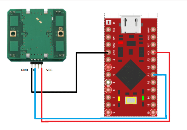
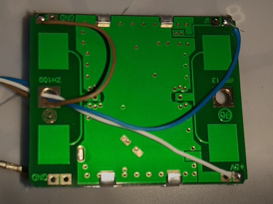
Connect the HB 100 microwave radar to Arduino according to the connection diagram.
| Arduino | HB 100 Radar Preamplifier |
| 5V | VCC |
| GND | GND |
| A1 | IF (signal out pin ) |
Testing
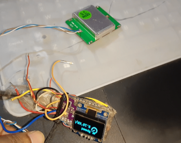
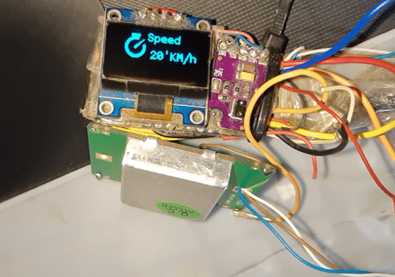
Now, upload the code to Arduino and power it. Now, upload the code to Arduino and power it. Whenever a sideways motion of the Arduino and associated components occurs with respect to the HB100 microwave Doppler radar, the resulting Doppler effect helps detect motion in real-time.
Congrats!! You have made a Doppler effect-based smart radar system that not only detects humans and other objects, but also measures their speed in real-time.
Real-World Applications of Doppler Radar:
- Object Detection and Speed Measurement: This radar system can detect and measure the speed of a variety of objects, including automobiles and pedestrians, in real time.
- Application Beyond Roads: Aside from traffic monitoring, this radar system has uses in sports (to measure ball or runner speed), industrial automation, and security.
- OLED Display for Real-Time Feedback: The OLED panel provides real-time feedback by displaying speed data, allowing users to rapidly monitor object velocity.
- Adjusting Sensitivity and Range: By tweaking the code and hardware parameters, you may tailor the system’s sensitivity and detection range to varied environments.
- Enhanced Features: For a more complex arrangement, try incorporating GPS for location monitoring or wireless connection modules to provide data remotely.
Download Source Code
This article was first published on 22 November 2021, and recently updated on 30 October 2024.
