


Solar Photovoltaic energy is available throughout the day while the Sun shines. However, this energy is highly fluctuating in nature. Also, lighting is mainly required during night when solar energy is not available. Therefore, there is a need for energy storage devices. The obvious choice is Lithium-ion battery. Even though Li-ion battery is the best option, there are some limitations:
-
Cost of Li-ion Battery is increasing year after year. Hence, these batteries will be mainly used for vehicles and mobiles. For stationary applications we have to find alternatives.
-
Li-ion Batteries can handle few thousand charge/discharge cycles. This implies the battery needs to be replaced after about 5 years

-
Re-cycling of Li-ion batteries is challenging and expensive.
-
India does not have Lithium mines. We are completely dependent on imports. Hence it becomes very important to explore other devices for energy storage.
-
Li-ion Batteries also use other metals such as Nickle and Cobalt etc. Therefore, these batteries are not environment friendly. Lot of mining is required to get these metals.
Proposed Alternative
Here we will explore use of Supercapacitors for energy storage for low power but widespread applications. Supercapacitors (or Ultra Capacitors) are also called as Electric Double-Layer Capacitors. They use porous carbon electrodes and store energy in the form of electric field. Unlike batteries which store energy in electrochemical form. These offer very large values of capacitance, measured in Farads. Typical working voltage of these capacitors is low (2.7 V). Following are their advantages:
-
Can be charged and discharged 100,000 times without losing storage capacity. Hence, they have long life of > 15 years.
-
Fast charging and discharging
-
Safer than batteries
-
Use easily available raw materials (eg carbon), hence environment friendly. No dependency on imports for expensive raw materials.
-
Easy to recycle
Limitations:
-
Low specific energy and lower working voltage
-
Linear discharge voltage
-
Slightly higher self-discharge
-
Higher cost. A 500 F capacitor presently costs about Rs 400 and 100 F capacitor costs about 175 rupees.
As of today, the cost of supercapacitors is significantly higher. Just for storing few Watt-Hours of energy we have to use several capacitors. Hence the cost of even small low power systems is fairly high. Some suggestions are given below for reducing the cost:
-
Mass Production: As discussed earlier, supercapacitors do not need expensive raw material. So, the high cost can be mainly attributed to low volumes of production. Therefore, there is a need to identify many applications which can generate big demand. As the production scales up, automatically the manufacturing cost will come down.
-
Redesign for slow charge/ discharge applications: Most supercapacitors available in the market are designed for handling high (in amps) charge/ discharge currents. Therefore, these Supercapacitors have thick terminals and large electrodes. However, in small solar applications the capacitor charge/ discharge currents are low (in milliamps). Hence, for such applications capacitor design can be optimized to reduce cost and size.
-
Higher value of capacitance for a given size and cost: By optimizing capacitor design for lower current applications, it may be possible to get higher capacitance in the same size and cost. This will increase the energy storage capacity for given size and cost.
-
Most of the Supercapacitors available in the market are imported. Stimulating the demand will attract Indian companies for local manufacture. The cost of locally produced capacitors will be much lower.
-
Government Subsidy to the manufacturers: Companies who want to manufacture supercapacitors, our government should provide some financial assistance for setting up manufacturing lines and for getting the latest design know how from established manufacturers.
Supercapacitor based Clock:
This is one of the best suited applications. Wall clocks need very low power. Wall clocks use one AA primary battery per year. Every house has few such clocks. So, we are consuming huge number of batteries every year containing hazardous chemicals. Further, these batteries are not properly disposed, hence pose big threat to the environment and health. Here, clock power supply design is proposed which uses solar energy and Supercapacitors. The aim here is to run the clock nonstop for at least 15 years under all weather conditions. This will eliminate the use of 15 AA cells and reduce hazardous chemical waste.
Design details:
Figure 1 shows the circuit diagram of proposed power supply. It consists of two small solar panels PV1 and PV2. Following are the specifications of these panels:
- Voltage at maximum power = Vmp = 5 V (Depends upon sunlight intensity)
- Current at maximum power = Imp = 100 mA
- Open circuit voltage = Voc = 6 V
- Size = 70 mm X 70 mm
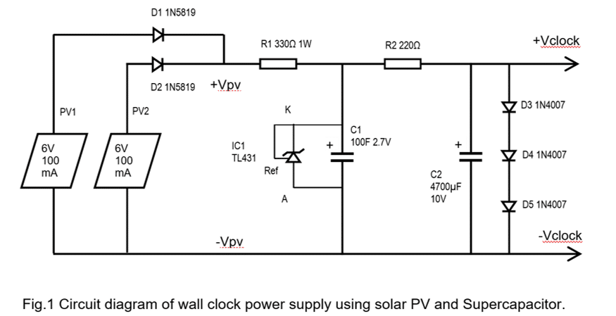
These panels are connected in parallel using two diodes D1 and D2 (1N5819). These Schottky diodes block current from one panel entering the other panel. The panel output voltage Vpv is fed to the Supercapacitor C1 (100F 2.7V) through current limiting resistor R1 (330Ω 1W). Voltage regulator IC1 (TL431) is connected across C1. It regulates the capacitor voltage to 2.5 V. IC1 ensures that the capacitor voltage never exceeds rated voltage of 2.7 V. Note that, diodes D1 and D2 also stop C1 from discharging into the panels, when there is no sunlight.
The output of capacitor C1 is connected to the clock terminals through current limiting resistor R2 (220Ω). Across these terminals three diodes D2, D3 and D4 (1N4007) are connected in series.
Total Forward voltage of D2, D3, D4 = 0.65 X 3 = 1.95 V
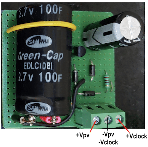
The clock movement operates in the range from 2 V down to 1V. Thus, the three diodes limit the voltage Vclock to less than 2V. C2 is used to reduce voltage dip whenever the movement draws pulse current. Fig 2 shows the assembled PCB.
The working of the above circuit will be clearer after looking at various waveforms shown in Figs 3, 4 and 5.

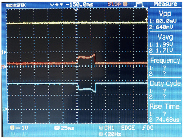
Figure 3 shows capacitor voltage (C1) and +Vclock voltage. These waveforms were captured without mounting the filter capacitor C2. Also, value of resistor R2 was changed to 100Ω. As seen in the figure, the capacitor voltage is stable at 1.99 V. We see dip in +Vclock voltage every second when the clock movement draws pulse current. Using math function of the oscilloscope, trace M (red) has been plotted which gives difference between Ch1 and Ch2. This waveform is the voltage across R2. Figure 4 shows the same waveform expanded.
From the red trace of Fig 4 we can calculate current through R2.
- Steady current through R2 and D3, D4, D5 = 0.2 V/ 100Ω = 2 mA
- Average pulse current = 0.6V / 100Ω = 6 mA
- Actual pulse current drawn by the clock movement = 6 – 2 = 4 mA
- Pulse duration = 30 msec
- Average current drawn by clock movement = 4 mA * 30 msec / 1000 msec = 0.12 mA.
- Average Power drawn by the clock movement = 0.12 * 1.71 = 0.2 mW
- Energy Consumed during 24 hours = 0.2 mW * 24 = 4.8 mWh
- Energy stored in the capacitor = 0.5 * C1 * V * V = 0.5 * 100 * 1.99 * 1.99 = 198 joules
- Energy stored = (198 / 3600) * 1000 = 55 mWh
From above calculations it is seen that, we have almost 11 times energy available in the capacitors on per day basis (under ideal conditions). However, there are self-discharge loss in the capacitor and losses in R2 and Diodes and residual voltage in the capacitor. Considering all the losses we can safely assume that the stored power in the capacitor will be sufficient for about 2 or 3 days. This factor helps in non-stop running of clock on rainy days when the sunlight is very less.
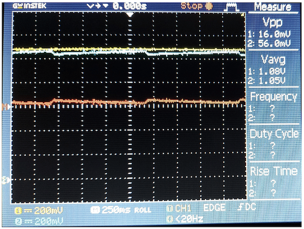
Figure 5 shows the filtered voltage waveform +Vclock. With C2 (4700 µF) connected at the output, the pulse peak voltage drops to less than 200 mV. Also, the value of resistance has been increased to 220Ω to reduce current through the diodes. These waveforms were captured when the C1 voltage was 1.08 V. Thus, it is clear that the clock works down to 1 V.
Interface:
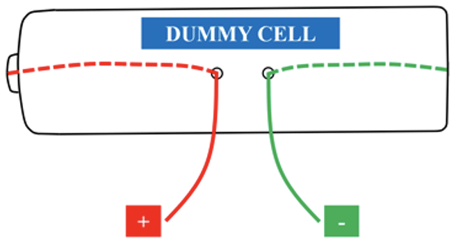
Figure 6 shows proposed AA size dummy cell made out of plastic material. It has metallic +ve and -ve terminals. Two wires are connected to these terminals and brought out through the holes provided. These wires are connected to +Vclock and -Vclock. User can simply insert this dummy cell in the clock moment.
Usage of the system:
Wall clocks are mounted inside the buildings hence they do not receive direct sunlight. Therefore, two PV panels have been used so that the circuit works on the diffused ambient light available inside the rooms. There is no need to mount the panels in the direct sunlight. The panels could be mounted on the same wall on which the clock is present. We have to ensure that throughout the day, the panels get good ambient light. If this light is not sufficient then we can mount the panels near the windows where light intensity is higher. Two PV panels also ensure that during rainy season the circuit works properly. Photograph of integrated system is shown in Fig. 7.
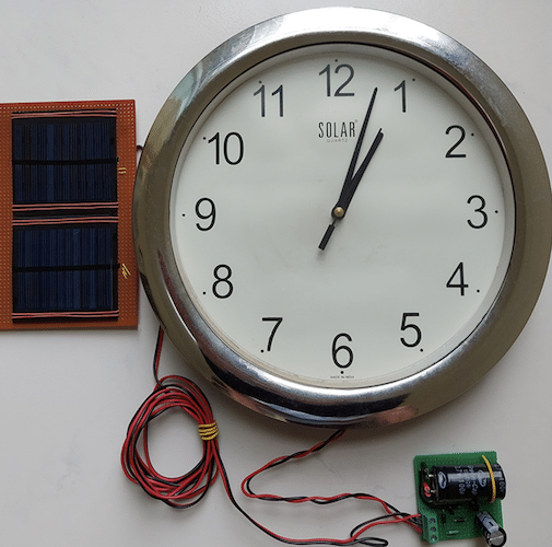
Fig.7 Photograph of system showing PV panels and clock interconnections.
Costing:
Assuming one cell is required per year, in 15 years of lifespan, we spend about 150 rupees on these cells.
The cost of proposed system is given below:
- Supercapacitor 100 F 2.7 V Rs 175
- Two 6V PV panels Rs 110
- PCB and small components Rs 35
- Total Rs 320
Note: These prices are for MOQ of 50 pieces. For one or two quantities prices may be much higher.
Thus, we see that the cost of proposed circuit is almost double as compared with the money we spend on batteries. We have to consider few more points regarding cost comparison which are as follows:
-
The life of PV panels is 30 years. Hence, we have to consider only half of it’s cost. As it can be reused for another 15 years along with another clock.
-
As of today, the production volume of supercapacitors is low, hence its cost is higher. If the production volume increases by many folds the cost will come down significantly.
-
By using the proposed circuit, we are eliminating the battery hazardous waste which otherwise goes into landfill. This poses threat to environment and health. We have to factor this environment cost in favor of the proposed design.
-
Supercapacitors do not require imported material. It mostly uses carbon; hence it will provide energy independence for our country.
-
Use of proposed circuit also eliminates the hassle of replacing the batteries. This may be a significant advantage for corporates, as they can reduce the manpower and need for keeping stock of batteries.
Optimization:
If there is some place inside the room, where direct sunlight is available for few hours then it may be possible to remove one PV panel. With direct sunlight, single panel can fully charge the capacitor quickly. This will help in reducing the cost to some extent. This will need long term testing in all seasons to ensure nonstop operation.
Power supply design for multiple clocks
In many companies there are multiple clocks mounted on the same wall. These clocks are used to show local time from different countries. Also, in wall clock showrooms, shops and repair shops there are several clocks running on individual batteries. Therefore, large number of cells are consumed in these shops. For such applications a single power supply is designed which can cater to many clocks. In this case, the cost of the circuit gets divided among all the clocks and the overall cost of the circuit comes down.
Circuit design for five clocks:
Figure 8 shows the circuit diagram of power supply which caters to five clocks.
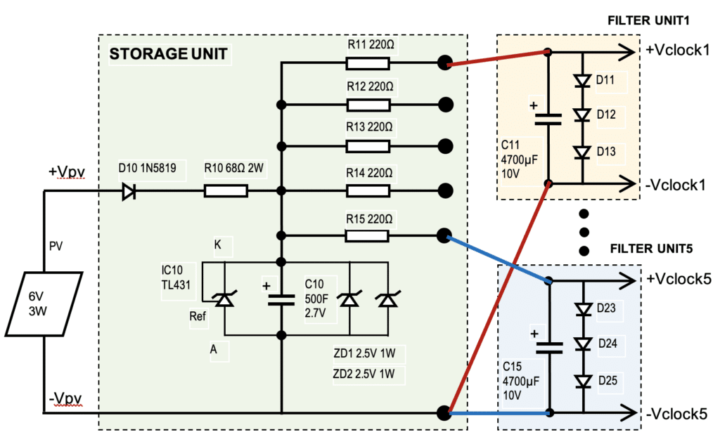
This design consists of two types of units. One storage unit and five filter units for five clocks. A 6V 3W solar PV panel is connected to the storage unit. Storage unit consists of a 500 F capacitor which is charged through diode D10 (1N5819) and resistor R10 (68 Ω 2W). Regulator IC10 (TL431) clamps the capacitor voltage to 2.5V. This regulator is rated for 100 mA current. Hence, additional Zener diodes DZ1 and DZ2 (2.5V 1W) are connected in parallel with the IC10. These Zener diodes can handle excess current.
Filter Units 1 to 5 have to be mounted very near to their respective clocks. The filter unit consists of filter capacitor of 4700 µF (C11 to C15, one for each filter unit). Also, each filter unit has three 1N4007 diodes connected in series (D11 to D25). The outputs of five filter units are connected to five different clocks.
The PV panel is mounted on a roof top or in a place where there is good sunshine. The storage unit is placed in a location inside the building, where the cable from PV panel comes inside the building. From storage unit, through current limiting resistors R11 to R15 thin cables are connected to the respective filter units. These wire lengths could be few tens of feet long. The capacitor in the filter unit will compensate for the cable inductance. In Fig 8, red wires connect R11 to filter unit 1. Similarly, blue wires connect R15 to filter unit 5.
Costing:
Costing for this design is given below:
- Supercapacitor 500 F 2.7 V Rs 400
- 6V 3W PV panel Rs 400
- PCB and small components Rs 200
- Total Rs 1000
The cost per clock is 1000 / 5 = 200 rupees. Thus, we can say that multiple clock design will provide better cost advantage. Thus, it can be implemented by all shop keepers so that demand for supercapacitors will get a boost.
Conclusion
Above design demonstrates use of supercapacitors for storing small amount of energy. As crores of clocks are being used, it offers big potential for reducing the use of chemical batteries. This will help in reducing hazardous waste. Also, it will generate demand for crores of supercapacitors. Many fold increase in production volume of these capacitors will bring down the cost. It will open up many other areas where these capacitors could be used for energy storage. Reduce dependence on imported Lithium and other costly metals. Each house will generate small amount of solar power and it’s cumulative effect will be significant. Need of the hour is to identify many more such applications.
Supercapacitors can contribute towards making Atmanirbhar and Swachh Bharat.

Vishal Sapre:
Two additions from my side…
1. A resistor of adequate value, instead of a dead short between the Cathode of TL431 and positive end of C1. TL431 is characterized for 100mA max current. Since C1 is large enough, it is necessary to have a resistor to limit current passing through TL431.
2. Split R2 into two parts, such that one part stays where it is shown, the other part is put between C2 positive and D3-Anode, instead of a dead short between the two. C2 is HUGE, so there should be something to limit current through the diode network (which seems to be good for 1A max). Whether the clock is connected or not, C2 will discharge via the Diode network, and in abscence of a limiting resistance, D3, D4, D5 may puncture causing a dead short across C2.
Best Regards,
Vishal Sapre
Vishal:
Further to my first comment, need to correct that, C2 will discharge through D3-D5 network, and will cause that leg to open. This will bring the complete 2.7V to bear upon the clock terminals.