


The aim of this project is to create an affordable and programmable smartwatch capable of tracking health data, providing real-time information, and enabling customization according to users’ preferences.
Leveraging the compact size and onboard sensors of the Indusboard Coin, along with additional components such as the GC9A0 display, MAX30100 SpO2 sensor, heart rate sensor, and temperature sensor, we can design a feature-rich smartwatch that meets these requirements.

Components
- IndusBoard: The Indus board serves as the core component of the smartwatch, offering a compact form factor and a variety of onboard sensors and GPIOs essential for building a versatile device.
- GC9A0 Display: The GC9A0 display provides a crisp and clear interface for users to interact with the smartwatch. Its high resolution and vibrant colors enhance the user experience, making it suitable for displaying health data, notifications, and other information.
- MAX30100 SpO2 Sensor: This sensor measures blood oxygen saturation levels (SpO2) and heart rate, enabling the smartwatch to monitor users’ health in real time. Accurate SpO2 readings are crucial for detecting potential health issues and ensuring users’ well-being.
- Heart Rate Sensor: Alongside the MAX30100 SpO2 sensor, the heart rate sensor further enhances health tracking capabilities, providing continuous heart rate monitoring during various activities and at rest.
- Temperature Sensor: The temperature sensor adds another dimension to health monitoring, allowing the smartwatch to track users’ body temperature and detect changes that may indicate illness or exertion.
- Wi-Fi Chip: Integrated with the Indusboard, the Wi-Fi chip enables connectivity, data synchronization, and the creation of a mesh network for collective health monitoring. It also facilitates over-the-air programming and customization of the smartwatch’s functions and features.
Functionality
- Health Tracking: The smartwatch can monitor vital signs such as heart rate, blood oxygen levels, and body temperature, providing users with insights into their overall health and well-being.
- Real-time Information: Users can access real-time data including time, date, weather updates, notifications, and activity tracking through the intuitive interface displayed on the GC9A0 screen.
- Customization: With programmable capabilities, users can customize the smartwatch’s UI, functions, and features according to their preferences and needs. They can also develop and install custom apps to extend functionality.
- Mesh Networking: The Wi-Fi chip enables the creation of a mesh network, allowing multiple smartwatches to communicate and share health data. This collective data can be analyzed to identify trends, patterns, and potential health risks within a community or group.
Preparing the Smartwatch Code
We first need to prepare the code to enable our smartwatch to display data and perform desired functions. We’ll be using Arduino for programming.
Step 1: Setting up Arduino IDE
- Download and install the latest version of the Arduino IDE.
- By default, the Arduino IDE does not include support for ESP boards.
- Visit the ESP website and follow the instructions to add the ESP board support to the Arduino IDE.
Step 2: Installing Required Libraries
We need several libraries to interface with the LCD and sensors and fetch time from the network. Open the Library Manager in Arduino IDE and install the following libraries:
- NTP Client
- MAX30100
- Arduino GFX
Step 3: Writing the Code
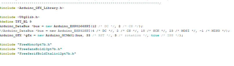
- Interfacing the LCD Display
- Use the Arduino GFX library to interface with the round LCD display.
- Include the library in your code.
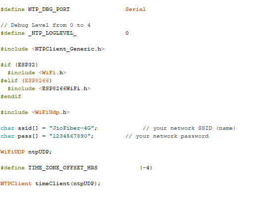
- Fetching Time from WiFi
- Use the NTP Client library to fetch time from the network via WiFi.
- Include this library in the code.
- Interfacing the MAX30100 Sensor
- Use the MAX30100 library to interface with the heart rate sensor.
- Include this library in your code.
Step 4: Hardware Setup in Code
- Configure the SPI bus pins and set the board type.
- For this project, we are using the Indus Board with the ESP32-S2 chip. On this board, any pins can be configured as SPI.
- Set the SPI pins (e.g., 21, 1, 2, 3, 4, 5) for the LCD display connection.
- Specify the LCD display driver, GC9A01, in the code.
Step 5: Setting Wi-Fi Credentials
- Define the Wi-Fi SSID and password to connect the smartwatch to your phone’s hotspot or home network.
- This connection enables the watch to fetch time from the NTP client server.
Step 6: Initializing Peripherals
- In the
setupfunction, initialize:- I2C communication for the MAX30100 sensor.
- SPI communication for the LCD display.
- NTP client for the clock synchronization.
Creating the GUI for the Smartwatch
Update the GUI elements and data dynamically to ensure the watch displays accurate and current information.
Updating Sensor and Time Data
- In the
loopfunction, continuously update the sensor readings and time data in real-time.
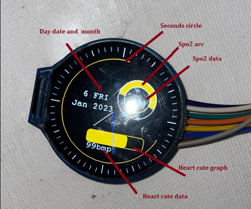
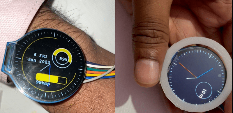
Designing the Interface
1. Create a graphical user interface (GUI) for the smartwatch to display:
- Health data (e.g., SPO2 and heart rate).
- Date and time information.
2. Customize the GUI as per your preference. For example:
- A circular clock face with two hands for minutes and hours.
- A circular arc representing seconds, which decreases in real-time.
- A round rectangle displaying heartbeat data.
- Text fields for the current day, month, and time-related data.
Real-Time Updates
- Update the GUI elements and data dynamically to ensure the watch displays accurate and current information.
Download Source Code
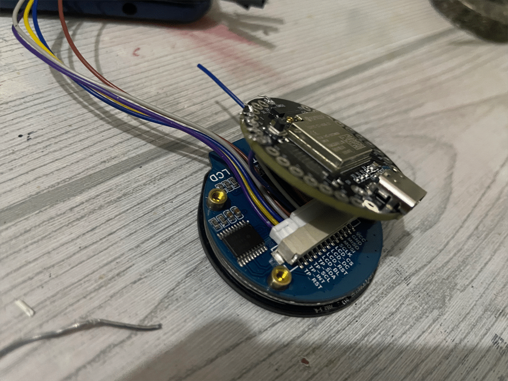
Connection
Now connect the MAX30100 sensor to Indusboard as following:
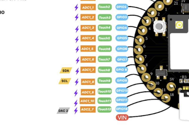
| Max30100 | Indusboard |
| VCC | 3V |
| GND | GND |
| SCL | 9 |
| SDA | 8 |
| Display | Indusboard |
| TFT MOSI | 21 |
| TFT_SCLK | 1 |
| TFT_CS | 2 |
| TFT_DC | 3 |
| TFT_RST | 4 |
| TFT_BL | 5 |
| VCC | 5V |
| BL | 3V |
| GND | GND |
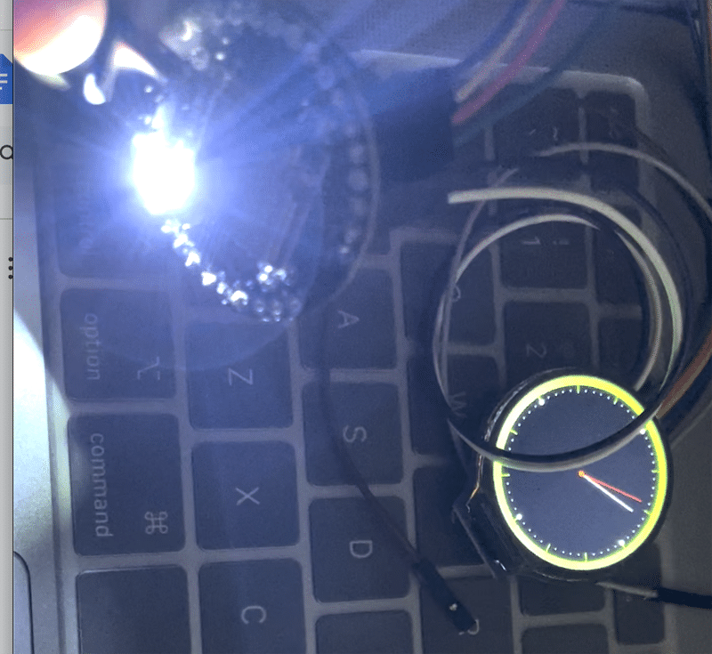
Testing Homemade Smartwatch
Now power the watch and you can see the details on the watch.
Check other Cool Smartwatch Projects:
- Smartwatch With Keyboard And Mouse Functionalities
- Programmable Smart Watch With Fitness Tracking
- IoT Smartwatch for Movement Tracking