


 You can make a bicolour LED night lamp powered by a supercapacitor that is based on joule thief circuit for charging the supercapacitor. Most night lamps go off when AC mains power fails. This night lamp works even when there is power outage. When fully charged, the supercapacitor can drive the LED light for long hours and even days.
Circuit and working
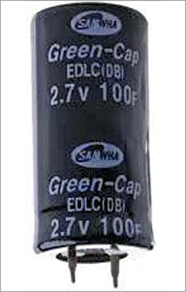
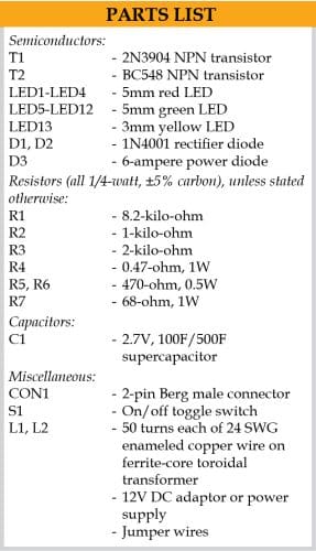
The circuit diagram of supercapacitor LED night lamp is shown in Fig. 2. It has transistors T1 (2N3904) and T2 (BC548), a toroidal transformer with coils L1 and L2, 2.7V/100F supercapacitor C1, thirteen LEDs (LED1 through LED13), Zener diode ZD1, and a few other components.

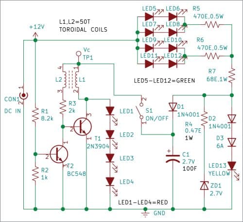
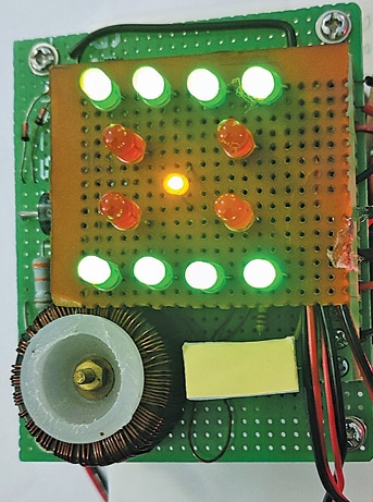
When the circuit is powered by 12V DC, only green LEDs (LED5 through LED12) glow. Yellow LED13 glows only when the supercapacitor is fully charged. When the power supply goes off, red LEDs (LED1 through LED4) glow.
The forward voltage of a red LED is about 2V only, unlike other LEDs like white or blue for which it is about 3V or more. So red LEDs are used here as they glow for longer time as compared to other LEDs. The author’s prototype uses four red LEDs which glow for six days with a fully charged capacitor. You can replace some or all the LEDs with white LEDs for brighter light but then you will have to charge the capacitor more often. Switch S1 is provided to switch off the lamp when it is not to be used.
Joule thief circuit is a low-cost and easy-to-build self-oscillating voltage booster that is widely used for driving small loads like LED lights. Its main components include a toroidal transformer, two transistors, a supercapacitor, and four red LEDs (LED1 through LED4). If we directly connect LEDs to the supercapacitor (Fig. 3), the LEDs will be on till the capacitor voltage drops to 2V (Vf). After that the stored energy remains unused.
Joule thief circuit here makes use of NPN transistor T1 and ferrite core transformer with coils L1 and L2. These coils are connected to capacitor voltage Vc. The other end of coil L1 is connected to collector of transistor T1 and coil L2 to its base through current-limiting resistor R3.
The current in coil L1 builds up and induces voltage in coil L2, driving transistor T2. Once the current in L1 stops increasing, there is no rate of change of current in it, so no voltage is induced in L2. This turns off transistor T1. The stored energy in L1 produces a large voltage spike and drives LEDs LED1 through LED4 that are connected to collector of T1. Once the stored energy in L1 is consumed by the LEDs, transistor T1 again turns on and the cycle repeats.
Construction and testing
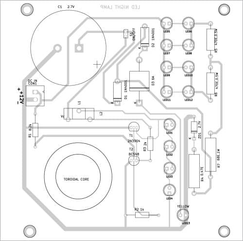
An actual-size PCB layout for the supercapacitor LED night lamp is shown in Fig. 4 and its component layout in Fig. 5. Supercapacitor C1 can be either mounted on the PCB or directly connected with two wires to the positive and negative terminals and placed suitably inside the cabinet.
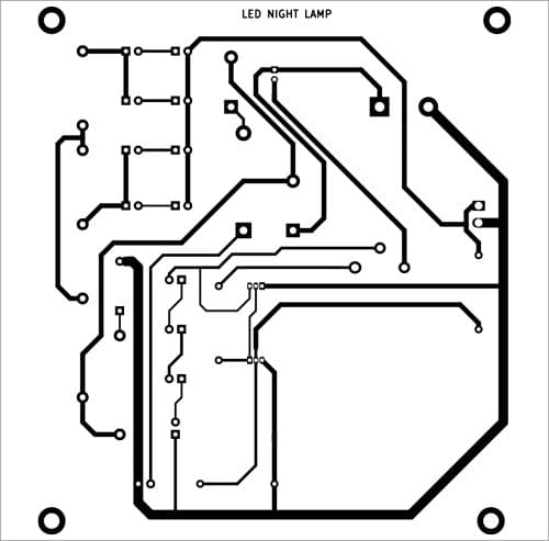
Download PCB and Component layout PDFs: click here
The four red LEDs are powered by joule thief circuit. In the author’s prototype, all the LEDs (LED1 through LED13) are mounted separately on a general-purpose PCB, with yellow LED (LED13) in the middle, four red LEDs (LED1 through LED4) forming the inner LEDs, and the green LEDs (LED5 through LED12) connected in series forming the outer LEDs. However, you can place the LEDs any way you like. You can also replace the green and red LEDs with white LEDs without changing the circuitry.
On connecting 12V DC source to CON1, the green LEDs will glow and supercapacitor C1 will start charging. Initially, yellow LED13 will not glow. It will glow only when supercapacitor has been charged. Depending on the current rating of 12V DC source, the charging can take ten to twenty hours.
When the 12V DC is disconnected, or the mains power is cut off, red LEDs (LED1 through LED4) glow as night lamp. These red LEDs can remain on for days, till the capacitor voltage drops to 2V or the circuit is switched off through on/off switch S1. You can measure the capacitor voltage at test point TP1 with a voltmeter.
Sani Theo is an electronics enthusiast and technical editor at EFY