


Tilt detection is a fundamental feature needed in various applications, including measuring the orientation of various parts and devices in an assembly. Due to the advent of sensors like the MPU6050 that is an integrated unit made up of a gyroscope and an accelerometer, it has become easy to ensure precise motion tracking and/or stabilisation. This article is associated with ‘Parishuddhi Yantra’, a funded project sponsored for ₹32,000 by the Student Startup and Innovation Policy (SSIP) 1.0, SSIP Cell, Government of Gujarat, India.
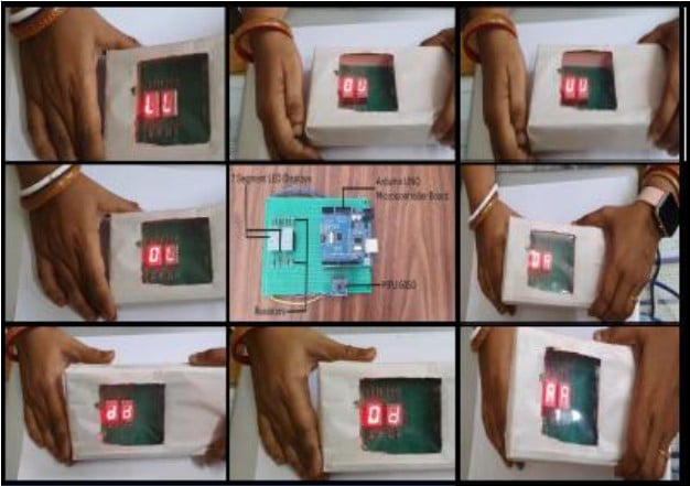
The proposed setup aims to create a real-time tilt detection system that can identify vital orientation in a predefined range of degrees and display the same. The featured image shows the author’s prototype of various experiments and their results. It demonstrates the mapping of various degrees (in X, Y and Z axes) to the predefined ranges of inclination across all directions.
| Components |
| MPU6050 gyroscope and accelerometer Measures acceleration along three axes and calculates tilt angles based on the sensor’s orientation. Arduino microcontroller Interfaces with the MPU6050 sensor, processes the data, and drives the seven-segment displays. Seven-segment displays (2 units) Displays the detected tilt direction in a human-readable format (CC, LL, RR, UU, dd, 0L, 0R, 0U, 0d). Resistors (1kΩ) Used to limit current and protect the seven-segment display segments. Connecting wires Establish electrical connections between the components. Power supply Provides the necessary 5V power to the system. |
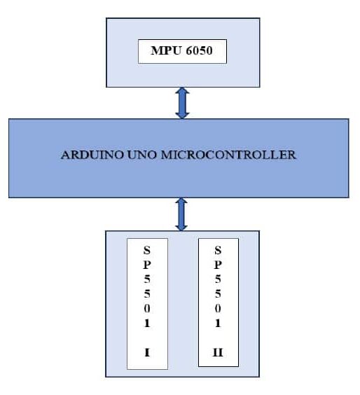
The proposed setup is used to check whether the angle of inclination of the Tiltsense device is within the specified range (user-defined). The MPU6050 sensor, a 6-axis motion tracking device, measures acceleration along the X, Y, and Z axes, as well as rotational velocity along three axes (roll, pitch, and yaw). This makes it ideal for a variety of motion-sensing applications, from simple tilt detection to more complex movement tracking. In this project, the MPU6050 sensor is used to capture tilt angles based on the gravitational pull along the X, Y and Z axes, which are then processed by an Arduino microcontroller. SP5501 is a common anode 7-segment display (they require voltage 0V to turn on the corresponding segment).
Tilt Detection Circuit Design
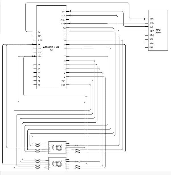
- MPU6050 to Arduino
VCC → 3.3V
GND → GND
SDA → A4 (for Arduino Uno)
SCL → A5 (for Arduino Uno) - Seven-segment display pins
First display: Pins connected to D0 through D6 of Arduino.
Second display: Pins connected to D7 through D13 of Arduino. - Resistors
Resistors are connected in series with each segment to limit current.
Overview