


The design offers advanced IGBT technology and customizable testing options for early-stage development and performance assessment in motor control.
The traction inverter is crucial in electric and hybrid electric vehicles, serving as the cornerstone for efficient and effective vehicle propulsion. It is a pivotal component that transforms direct current (DC) from the vehicle’s battery into alternating current (AC) to power electric motors. Beyond mere power conversion, traction inverters control motor speed and torque, enable regenerative braking, and enhance overall energy efficiency. Their ability to seamlessly integrate with various vehicle systems, including advanced driving technologies, marks them as essential in the evolution of electric vehicle performance and functionality. This makes the traction inverter a component and a key enabler in the journey towards more sustainable and advanced automotive technologies.
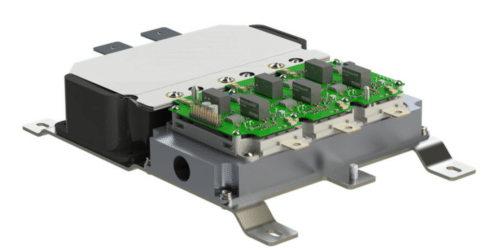
The VE-Trac Direct Evaluation Kit by Onsemi comprises a VE-Trac Direct power module attached to a cooling jacket, a 6-channel Gate driver board, and a DC Link capacitor. The kit does not come with a PWM controller or external current sensors. Users are required to provide their own PWM controller to operate the system. Additionally, external current sensors are necessary for closed-loop motor control. The kit offers users the opportunity to assess the performance of the VE-Trac Direct power module in the initial stages of inverter development. It can be utilized as a double pulse tester for measuring key switching parameters or as a 3-phase inverter for motor control applications.
The kit is designed for EV/HEV Traction Inverter applications, capable of handling up to 150 kW. It includes the VE-Trac Direct NVH820S75L4SPB, featuring an 820 A, 750 V Field stop 4 IGBT/Diode chipset. The design also contains an automotive isolated high current and high-efficiency IGBT gate driver, the NCD57000, with internal galvanic isolation. Additionally, it incorporates basic protection features like Over Temperature Protection (OTP) and Desaturation (Desat). To complement these components, the design is equipped with a custom Film DC Link capacitor, rated up to 500 VDC and 500 µF, ensuring efficient power storage and management within the system.
The Gate Driver Board in this setup operates with a control power ranging from 9 V to 15 V. The DC Link Voltage varies from 0V to 500V, with the upper limit set by the capacitor’s capacity. It can handle a peak collector phase current (1ms) from -1640 A to 1640 A, constrained by the maximum IGBT/FWD junction temperature, which ranges from -40°C to 175°C. After a short circuit event, a mandatory wait time is 1 second. The PCB temperature is maintained at 85°C, and the system operates at a switching frequency of 12 kHz. Additionally, the coolant temperature is regulated between -40 °C and 65°C.
Onsemi has tested this reference design. It comes with a Bill of Material (BOM), schematics, etc. You can find additional data about the reference design on the company’s website. To read more about this reference design, click here.